
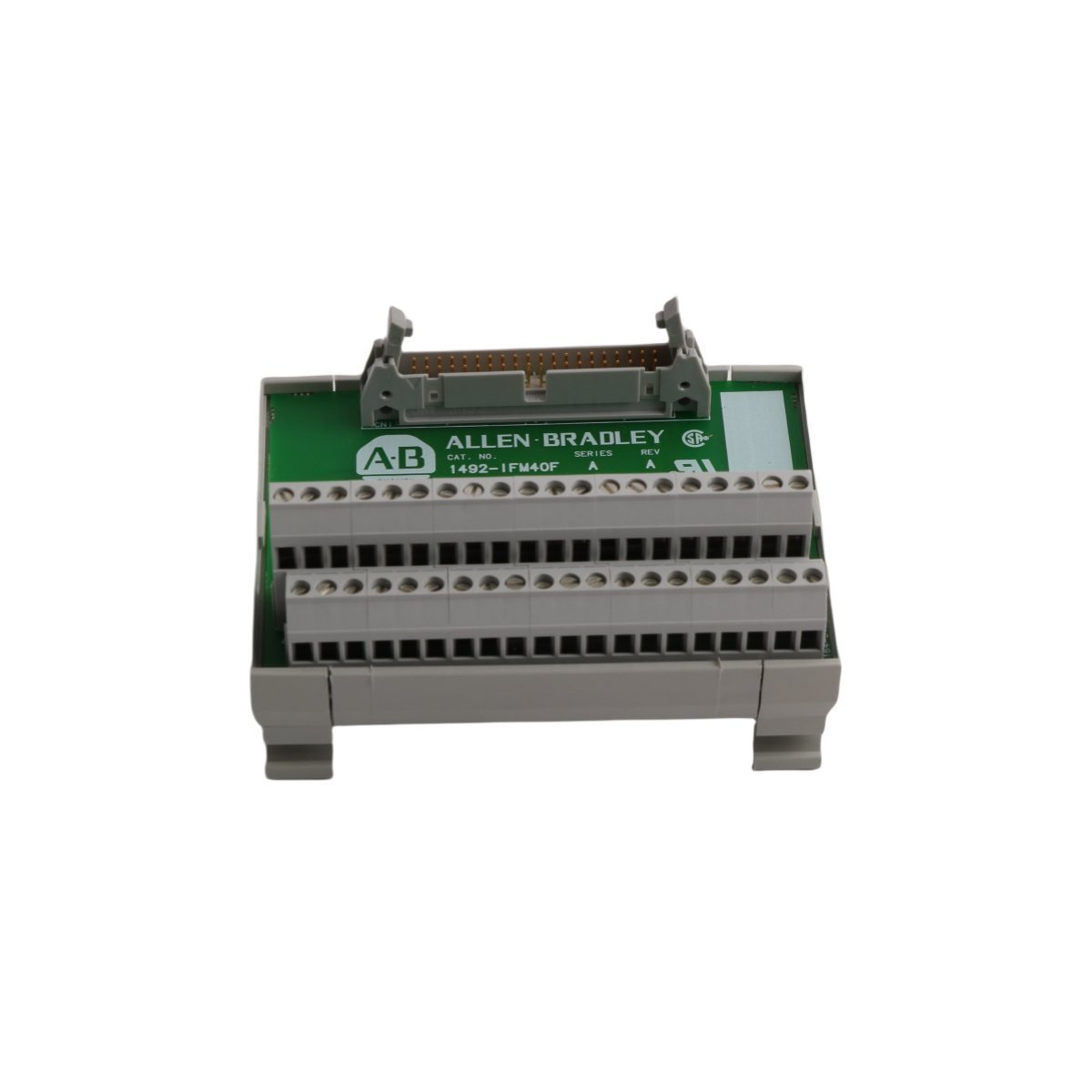
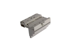
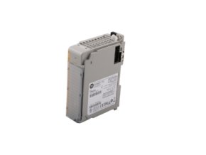
Allen Bradley 1492-IFM40F-FS-2 1492 Fusible Interface Module
Sale!Find out details for the Allen Bradley 1492-IFM40F-FS-2 Wiring Systems Module. It features Brand New condition, Original Stock, 40 contacts, 10-30 V operating range, and supports Global Shipping.
99 in stock


- DIN Rail Mechanical Stability: Mount the module securely onto standard #3 DIN rail. Install mechanical end anchors on both sides of the module housing to prevent lateral shifting along the rail assembly during peak vibrational periods.
- Conductor Termination Protocol: Strip all field wiring conductors uniformly. Insert the copper conductors completely into the designated clamping zone of the fixed terminal block, and torque each terminal screw to the official manufacturer specification to ensure constant physical connection.
- Loop Separation and Grounding: Route the 10-30 V low-voltage discrete wiring away from high-voltage AC motor lines or variable frequency drive cables inside the cabinet tracking. Earth the DIN rail itself to the main enclosure backplate to mitigate potential electromagnetic interference.
- Fuse Insertion Inspection: Before applying field loop voltage to the system, verify that all fuses are seated firmly inside their respective clips and match the nominal current rating needed for the downstream industrial load devices.
Allen Bradley 1492-IFM40F-FS-2 Wiring Systems Modules
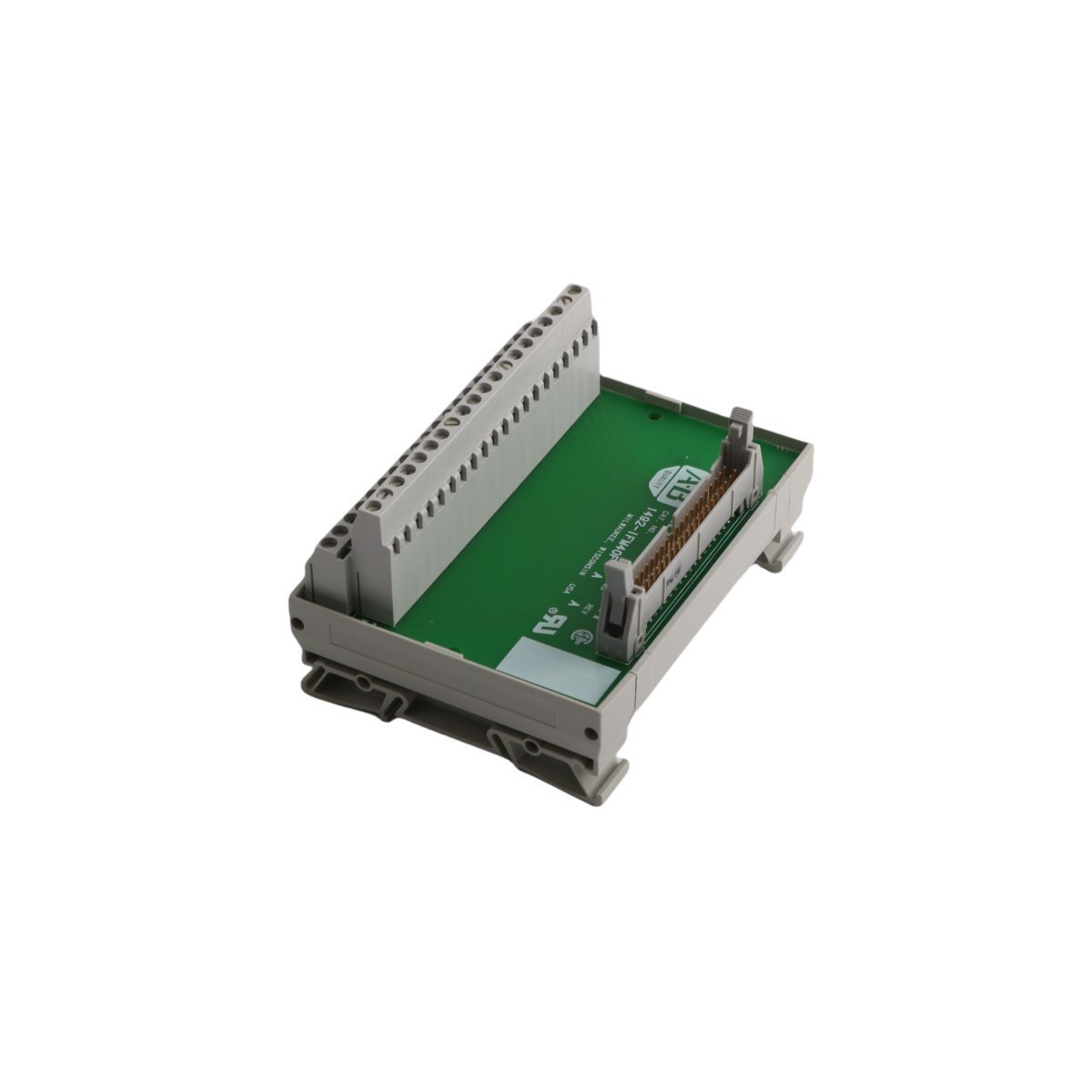
Configured for digital wiring routing and field signal distribution in industrial automation control networks, the Allen Bradley 1492-IFM40F-FS-2 (1492-IFM40F-FS-2 Wiring Systems Module) provides direct physical/electrical execution. This 40-contact fusible interface module operates in direct connection with 1746 series I/O modules, establishing individual interface circuits via its fixed terminal block architecture. The design assigns one field-side terminal to each I/O point, allowing engineers to route and terminate I/O device commons remotely from the main digital control enclosure.
Hardware Specifications
| Parameter | Specification |
|---|---|
| Model | 1492-IFM40F-FS-2 |
| Brand | Allen Bradley |
| Origin | USA |
| Weight | 0.68 kg |
| Dimensions | 3 x 17 x 27 cm (Enclosure dimensions: 8.27 x 3.27 x 2.78 inches) |
| Operating Temp | Up to 60 deg C maximum |
| Power Consumption | Passive (Draws no internal control power) |
| Operating Voltage Range | 10 to 30 VAC or VDC |
| Current Capacity per Circuit | 2 A maximum |
| Total Module Current Capacity | 12 A maximum |
| Connection Type | 40-contact fixed terminal block |
| Protection Components | Integrated fuse clips and visual status LEDs |
| Mounting Base | Standard #3 DIN rail |
| Certifications | CE, cULus, UL, Class 1 Division 2 Hazardous Locations |
| Temperature Code | T3C |
| System | PLC / 1746 I/O Platform |
Backplane Integration and Deterministic I/O Scaling
The Allen Bradley 1492-IFM40F-FS-2 provides high-density I/O scaling by consolidating complex discrete wiring point-to-point topologies into standard pre-wired cable assemblies. The module maintains zero latency in protocol execution because it acts as a passive electrical termination matrix rather than a digital processor. However, the total backplane bus current limitations dictate that total current loop aggregation across all 40 channels must never exceed the 12 A thermal boundary. The onboard diagnostic LEDs draw microscopic current directly from the 10-30 V discrete line voltage loop to maintain real-time visual verification of fuse integrity at each terminal block junction.
Frequently Asked Questions
Q: Does the 1492-IFM40F-FS-2 require special firmware flash compatibility or configuration software?
A: No. The unit functions purely as a mechanical and electrical interface bridge. It contains no internal microprocessors or logic chips, which completely eliminates the need for firmware files, driver installations, or active software validation.
Q: Can an operator field-replace the individual fuses and visual indicator status LEDs?
A: Field technicians can easily replace the fuses within the integrated fuse clips after disconnecting the line power source. The module hardwires the status LEDs into the protection circuit matrix; therefore, if an LED component fails, the module requires complete hardware replacement to restore diagnostic visibility.
Q: What are the consequences if the continuous current per circuit exceeds the 2 A limit?
A: Exceeding 2 A on an individual loop triggers the integrated fuse protection, opening the circuit to prevent physical degradation of the internal printed circuit board traces. Continuous overload without proper fusing will generate excessive thermal energy, risking permanent damage to the structural terminal block insulation.
Field Installation Guidelines
| Weight | 0.68 kg |
|---|---|
| Country of Origin | USA |
| Dimension | 3 x 17 x 27 cm |
Reviews
There are no reviews yet.