
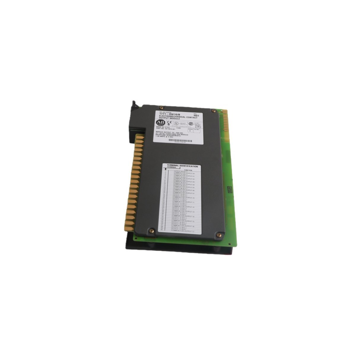
1771-OW Allen-Bradley PLC-5 Selectable Contact Output Module
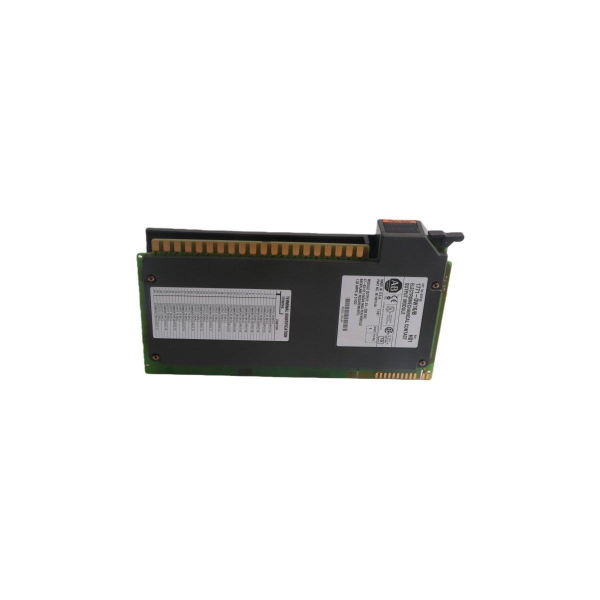
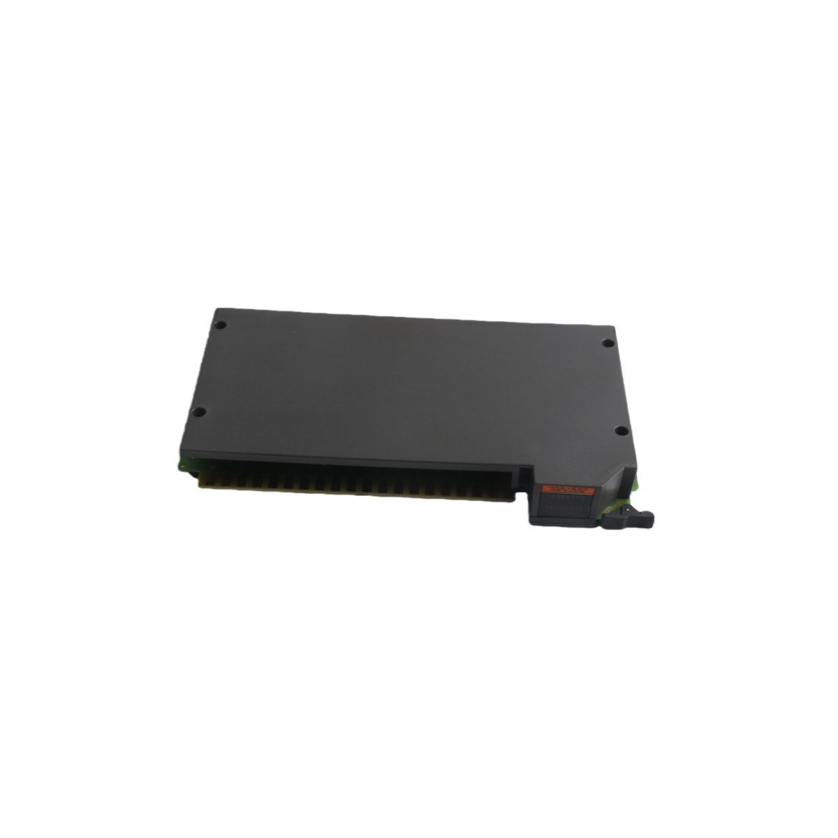
Sale!The Allen-Bradley 1771-OW PLC-5 selectable contact output module offers 8 relay outputs in 4 isolated groups. Brand New, Original Stock, Global Shipping.
99 in stock


- Chassis Alignment and Insertion: Align the printed circuit board with the upper and lower plastic chassis card guides. Push the module firmly inward until the backplane edge connector fully seats and the module locking latch clips securely to the chassis rail.
- Shield Grounding Regulations: Terminate all inductive field cabling shields at the designated enclosure ground bar. Keep low-voltage logic signal wires completely separate from high-current AC output loops to eliminate electromagnetic cross-talk.
- Wiring Terminal Verification: Tighten all screw terminal blocks on the swing-arm assembly to the recommended torque specifications, ensuring that continuous vibrations inside the plant do not loosen electrical load paths over long operational periods.
Allen-Bradley 1771-OW Selectable Contact Output Module
The Allen-Bradley 1771-OW serves as the primary 1771-OW Selectable Contact Output Module utilized to execute discrete relay loop switching across PLC-5 platform backplanes. The hardware physical interface arranges eight relay output channels into four distinct isolated groups, allowing the circuits to isolate independent load loops simultaneously. By routing configurations directly on the hardware assembly, plant technicians toggle each contact point between normally open (N.O.) and normally closed (N.C.) switching logic to drive external field devices.
Hardware Specifications
| Parameter | Specification |
|---|---|
| Model | 1771-OW |
| Brand | Allen-Bradley |
| Origin | USA |
| Weight | 0.9 kg |
| Dimensions | 3.5 x 13.0 x 14.5 cm |
| Operating Temp | 0 to 60 deg C |
| Power Consumption | 700 mA maximum backplane current |
| Channels | 8 relay outputs (4 isolated groups of 2 channels) |
| AC Voltage Range | 24-138 VAC (resistive loads) |
| DC Voltage Range | 24-125 VDC |
| Continuous Current | Up to 1 A per channel |
| Configuration | Separately configurable N.O. or N.C. per point |
| System Platform | PLC-5 |
Deterministic Network Traffic and I/O Density Scaling
The Allen-Bradley 1771-OW maintains fixed backplane bus communication velocity during intensive I/O density scaling sequences within the PLC-5 chassis. The module transfers output image table states from the CPU memory across the parallel backplane structure, shielding the mechanical relay coils from non-deterministic external communication latencies. Because the hardware operates with rigorous firmware flash compatibility parameters across the legacy product range, it enforces predictable coil execution speeds even when communicating through upstream network links connected via an Ethernet router module.
Frequently Asked Questions
Q: How does a technician alter the channel output orientation between N.O. and N.C. states?
A: The design permits direct mechanical adjustments on the physical module body. Operators modify the specific internal terminal configuration jumpers for individual channels prior to sliding the assembly into the rack.
Q: What method prevents the insertion of an incorrect module type into the designated chassis slot?
A: The system utilizes plastic keying bands positioned between specific pin pairs on the chassis backplane connector, which physically blocks alternative modules from seating into the live backplane.
Q: Can individual channels switch different voltage types simultaneously?
A: Yes. Because the eight channels reside within four isolated groups, engineers can run separate power sources (e.g., 120 VAC on one group and 24 VDC on another) without suffering cross-group voltage leakage.
Field Installation Guidelines
| Weight | 0.9 kg |
|---|---|
| Country of Origin | USA |
| Dimension | 3.5 x 13 x 14.5 cm |




Reviews
There are no reviews yet.