
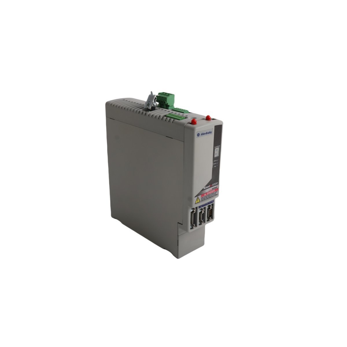
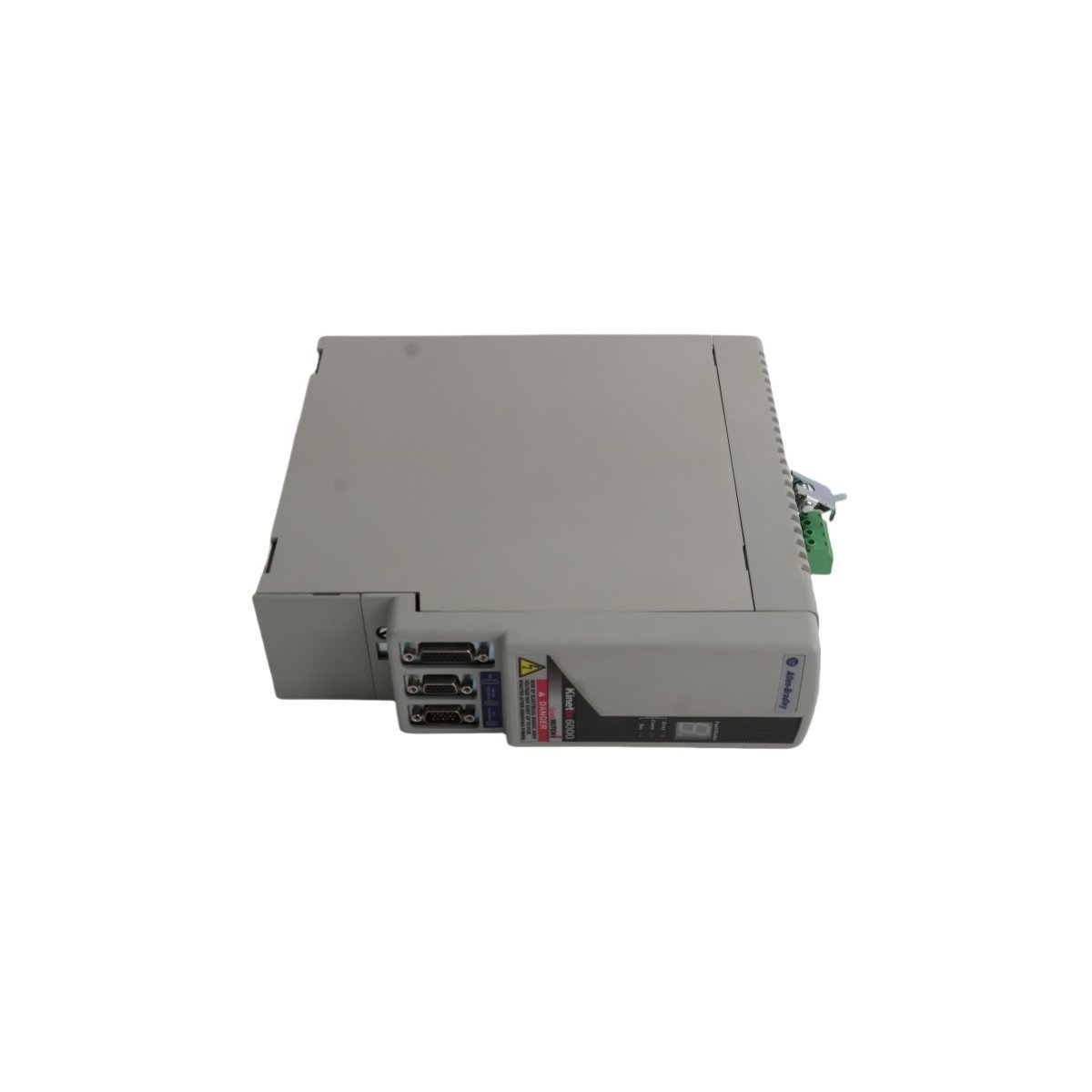
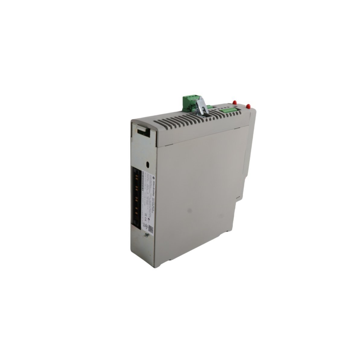
2094-BM01-M Allen Bradley Kinetix Modular Axis Power Module
Sale!Technical datasheet for the Allen Bradley 2094-BM01-M Modular Axis Module. Brand New, Original Stock, global shipping available.
99 in stock


- Power Rail Alignment: Clean all backplane power rail pins prior to installation. Slide the module straight back onto the Kinetix power rail guides until the locking mechanisms seat fully, ensuring zero mechanical skew to prevent high-resistance contact arcs under 15.3 A peak loads.
- Shielding Termination: Strip motor feedback and auxiliary feedback cables according to standard electromagnetic compatibility guidelines. Ground the braided cable shields directly to the chassis ground plate utilizing the integrated shield clamps to minimize PWM electrical cross-talk.
- Enclosure Ventilation Layout: Utilize the specified loading power dissipation metrics (up to 126 W at 100% load) to calculate cabin cooling requirements. Maintain the specified physical clearance gap above and below the axis module housing to enable unrestricted air movement across the chassis structure.
- Safety and I/O Wire Routing: Route low-voltage safety input wiring and door monitoring lines through isolated wire ducts separate from the 400 VAC motor power conduits to eliminate inductive noise coupling into the safety loops.
Allen Bradley 2094-BM01-M Modular Axis Module
The Allen Bradley 2094-BM01-M, also cataloged as the 2094-BM01-M Modular Axis Module, operates as a dedicated hardware component for multi-axis servo drive control within Kinetix 6200/6500 drive platforms. The module mounts directly onto a Kinetix power rail interface adjacent to the Integrated Axis Module (IAM), where it establishes direct electrical connection to draw DC bus power and activate its internal motion circuitry. Operating inside a 400 VAC nominal voltage category, this hardware executes precise rotor positioning and torque regulation via pulse-width modulation (PWM) switching commands transmitted through feedback loops to connected servo motors.
Hardware Specifications
| Parameter | Specification |
|---|---|
| Model | 2094-BM01-M |
| Brand | Allen Bradley |
| Origin | USA |
| Weight | 2.9 kg |
| Dimensions | 7 x 25.5 x 28.5 cm |
| Continuous Current | 6.1 A |
| Peak Current | 15.3 A |
| Short-Circuit Current Rating | 200,000 A (rms) symmetrical |
| Module Efficiency | 98% |
| Velocity Loop Bandwidth | 500 Hz |
| Current Loop Frequency | 1300 Hz |
| Pulse Width Modulation (PWM) Frequency | 4 kHz |
| Internal Shunt Continuous Power | 50 W |
| Internal Shunt Peak Power | 5.6 kW |
| Internal Shunt Resistor Value | 115 Ohms |
| Shunt Operation Voltages | Shunt On: 805 VDC / Shunt Off: 765 VDC |
| Module Capacitance | 150 uF |
| Capacitance Energy Absorption | 19 Joules |
| Power Output @ 20% Loading | 57 W |
| Power Output @ 40% Loading | 75 W |
| Power Output @ 60% Loading | 90 W |
| Power Output @ 80% Loading | 108 W |
| Power Output @ 100% Loading | 126 W |
| Communication Service | Ethernet router compatibility via control module |
| System | Kinetix 6000 / Motion Control Platform |
Deterministic Motion Networks and Integrated Safety Control
The Allen Bradley 2094-BM01-M incorporates a modular architecture that separates the underlying power electronics from the upper control module layer, enabling direct interface expansion with EtherNet/IP deterministic networks. The internal microprocessor controls power distribution dynamically across the system backplane, matching high I/O density scaling requirements while sustaining a high current loop update rate. Dedicated hardware internal pathways process safety-critical motion metrics autonomously, enabling integrated speed limiting and monitoring functions without adding execution latencies to the primary control loop. The embedded circuitry monitors real-time feedback data to validate Safe Maximum Speed, Safe Maximum Acceleration Monitoring, Safe Direction Monitoring, Zero Speed Monitoring, Enabling Switch Control, and Door Monitoring and Control, immediately broadcasting diagnostic fault messages across the bus when parameters breach configured safety profiles.
Frequently Asked Questions
Q: How does the 2094-BM01-M achieve firmware flash compatibility when deployed alongside older Kinetix 6000 drives? A: The power module itself houses fixed hardware and power switches. Firmware flash compatibility resides wholly within the detachable control module that slides onto the front face of the 2094-BM01-M. Technicians must flash the control module to match the system software revisions, while the underlying axis module requires no direct firmware manipulation.
Q: Can the 2094-BM01-M operate as a standalone drive without an Integrated Axis Module (IAM)? A: No. The 2094-BM01-M functions strictly as a secondary Axis Module (AM). It lacks an internal AC-to-DC rectifier circuit and requires direct connection to a Kinetix power rail shared with a primary IAM, which supplies the regulated VDC bus voltage needed to energize the module internal capacitance.
Q: What physical indicator confirms an internal shunt overload condition on the module? A: The module utilizes its enhanced diagnostic display architecture to broadcast specific alphanumeric error codes corresponding to shunt thermal limits. When peak shunt power exceeds 5.6 kW or continuous absorption passes 50 W, the internal hardware activates a protective fault routine, stopping PWM switching output to shield the 115 Ohm resistor.
Field Installation Guidelines
| Weight | 2.9 kg |
|---|---|
| Country of Origin | USA |
| Dimension | 7 x 25.5 x 28.5 cm |


Reviews
There are no reviews yet.