
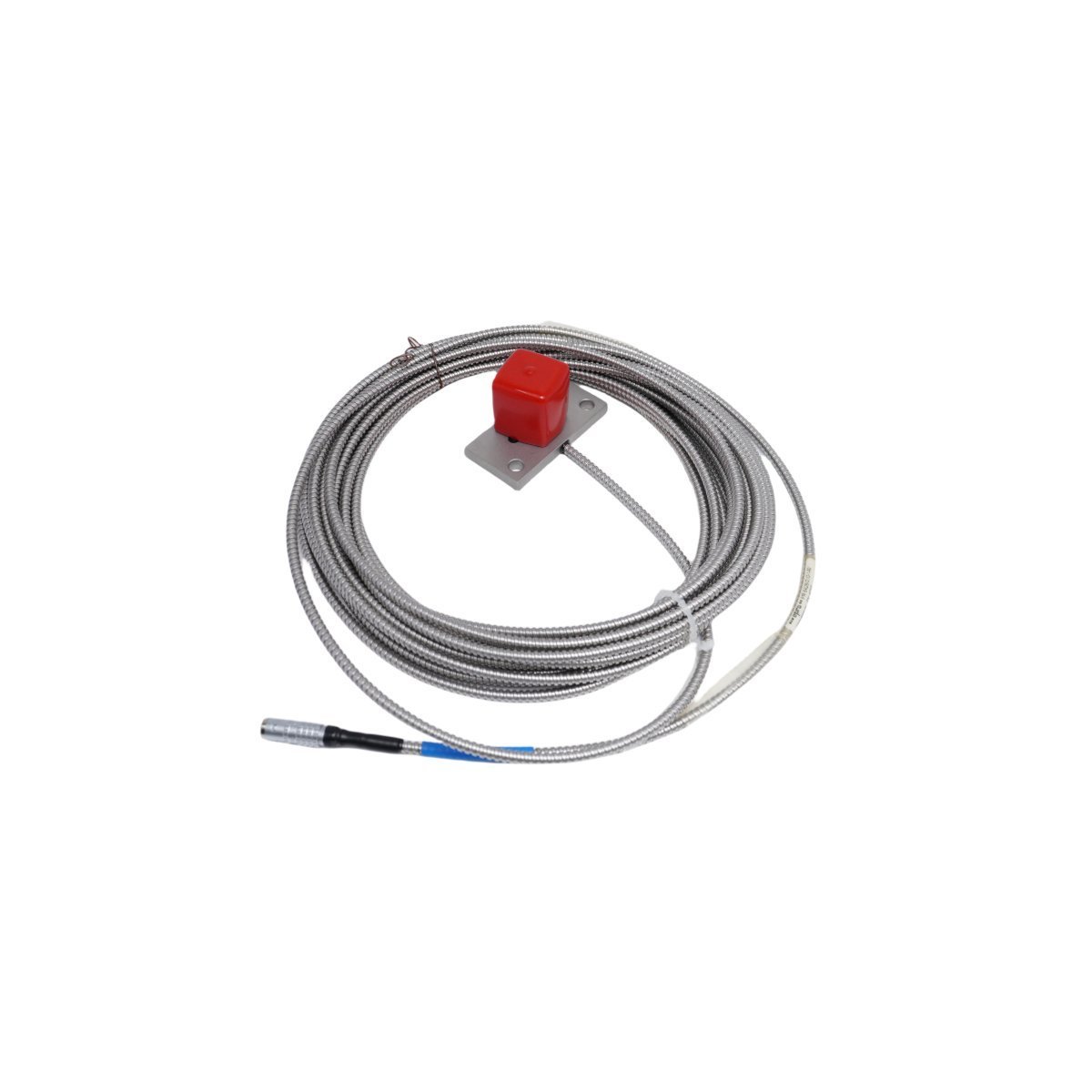
PR6426/010-140 Emerson EPRO Eddy Current Displacement Sensor
Sale!Emerson PR6426/010-140 EPRO Eddy Current Vibration Sensor for machinery protection systems. Brand New hardware in Original Stock with fast Global Shipping available worldwide.
99 in stock


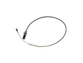
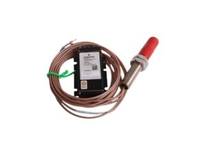
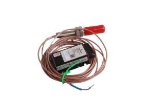
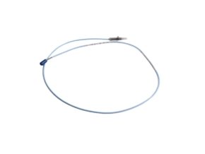
Emerson PR6426/010-140 EPRO Eddy Current Vibration Sensor
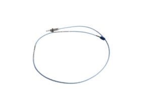
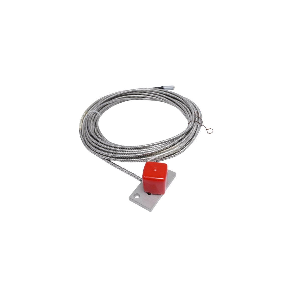
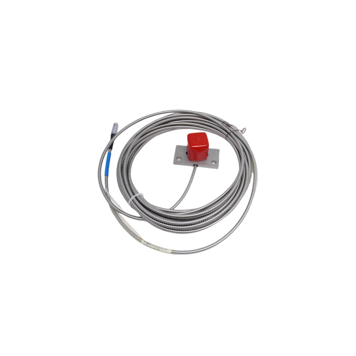
The Emerson PR6426/010-140, also cataloged as the PR6426 Eddy Current Displacement Sensor, operates as a dedicated hardware component for non-contact shaft vibration and displacement measurement within EPRO Machinery Protection Systems. The probe generates a high-frequency electromagnetic field at the sensor tip to measure physical distance variations relative to a conductive target material. Engineers configure this non-contacting transducer to convert mechanical shaft motion into precise voltage signals, thereby supplying critical dynamic data directly to continuous turbomachinery monitoring electronics.
Suffix Breakdown & Model Matrix
| Part Number / Code | Component Specification | Functional Description |
|---|---|---|
| PR6426 | Base Model Series | Non-contact eddy current proximity transducer family |
| /010 | Cable Length Option | Integrated armor/cable configuration identifier |
| -140 | Mounting Thread / Case Variant | Mechanical casing and threaded body adaptation code |
Hardware Specifications
| Parameter | Specification |
|---|---|
| Model | PR6426/010-140 |
| Brand | Emerson |
| Origin | USA |
| Weight | 0.4 kg |
| Dimensions | 24 x 17 x 6.5 cm |
| Operating Temp | -35 to 180 deg C |
| Power Consumption | Powered via driver/signal conditioner (-24 VDC supply loop) |
| Series | EPRO Machinery Protection System |
| Sensor Diameter | 12 mm tip (32 mm probe series family) |
| Target Material | Ferromagnetic steel (42CrMo4 calibration standard) |
| HS Code | 8537101190 |
Probe Calibration & Rotor Dynamics Measurement
The Emerson PR6426/010-140 utilizes precise eddy-current probe scaling to deliver linear voltage output proportional to target distance. Proper operation requires strict gap voltage validation (-10 VDC targets) during initial mechanical positioning, which centers the sensor within its linear measurement range. The probe output drives signal conditioners to monitor complex rotor dynamics, including relative shaft vibration, radial position, and axial thrust displacement. Furthermore, optimized internal coil shielding prevents cross-talk suppression issues when technicians install adjacent transducers in high-density bearing housings.
Frequently Asked Questions
Q: How do technicians verify correct mechanical positioning before energizing the signal driver?
A: Technicians connect a multimeter to the driver output terminals and adjust the probe insertion depth until the static reading reaches the specified -10 VDC gap voltage bias point.
Q: What precautions prevent cross-talk when installing multiple probes in the same bearing housing?
A: Installers must maintain a minimum physical center-to-center spacing between probe tips or orient adjacent probes at 90-degree angles to avoid electromagnetic interference between adjacent sensing fields.
Field Installation Guidelines
Installers must thread the probe body into the rigid mounting bracket using calibrated torque tools to prevent casing deformation. Route the extension cable through protective flexible conduit and secure it against high-vibration structural members.
During signal wiring, technicians must isolate the coaxial cable shield from local machine ground and terminate it exclusively at the driver module earth terminal. Maintain a minimum bend radius of 30 mm on armored cables to avoid internal conductor damage. Keep all probe interconnecting lines separated from high-voltage motor supply conductors to eliminate transient noise coupling.
| Weight | 0.4 kg |
|---|---|
| Country of Origin | USA |
| Dimension | 24 x 17 x 6.5 cm |
Reviews
There are no reviews yet.