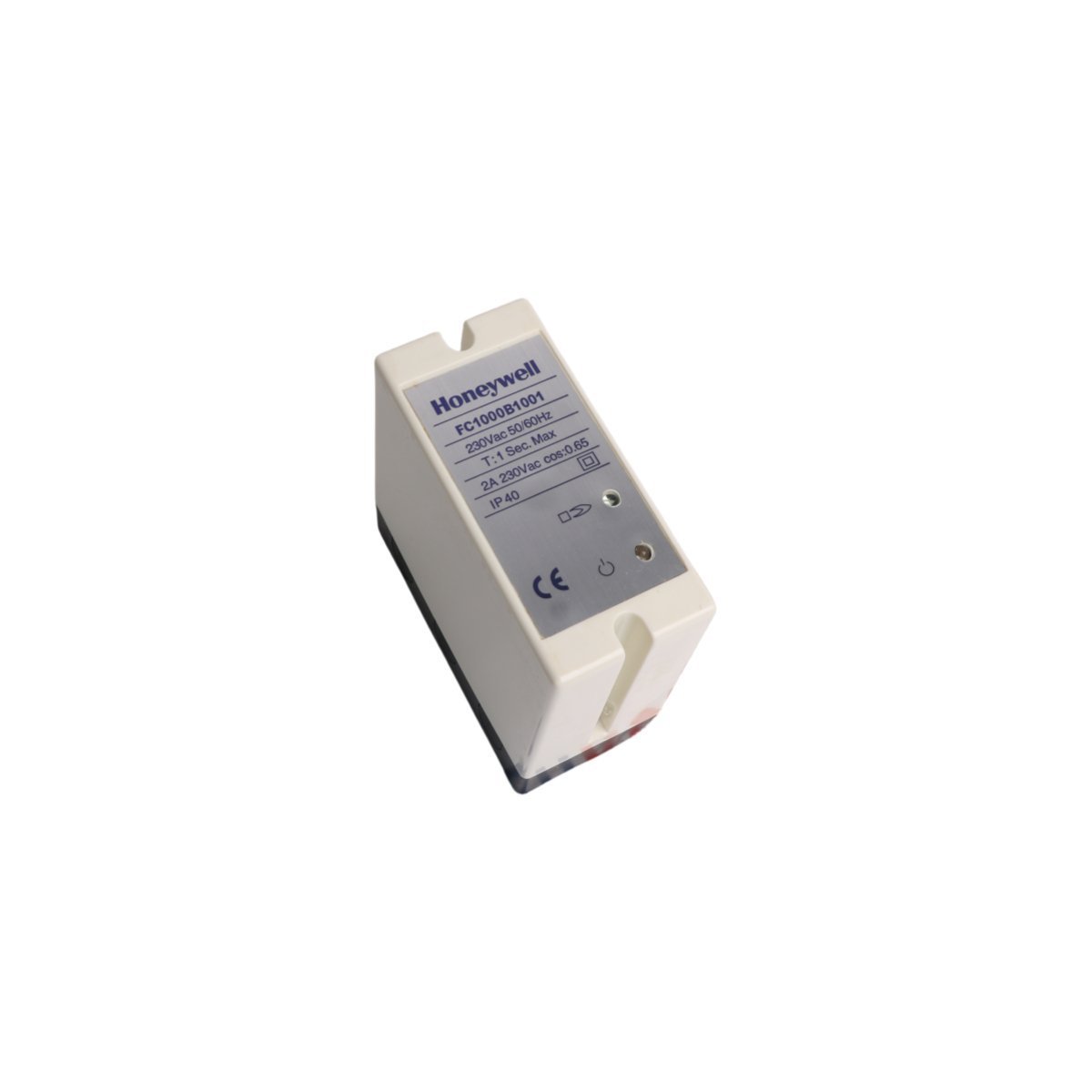
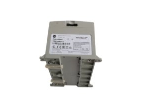
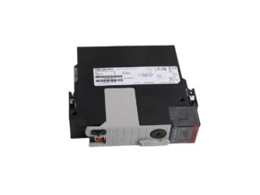
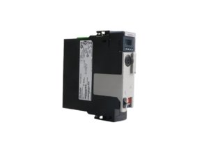
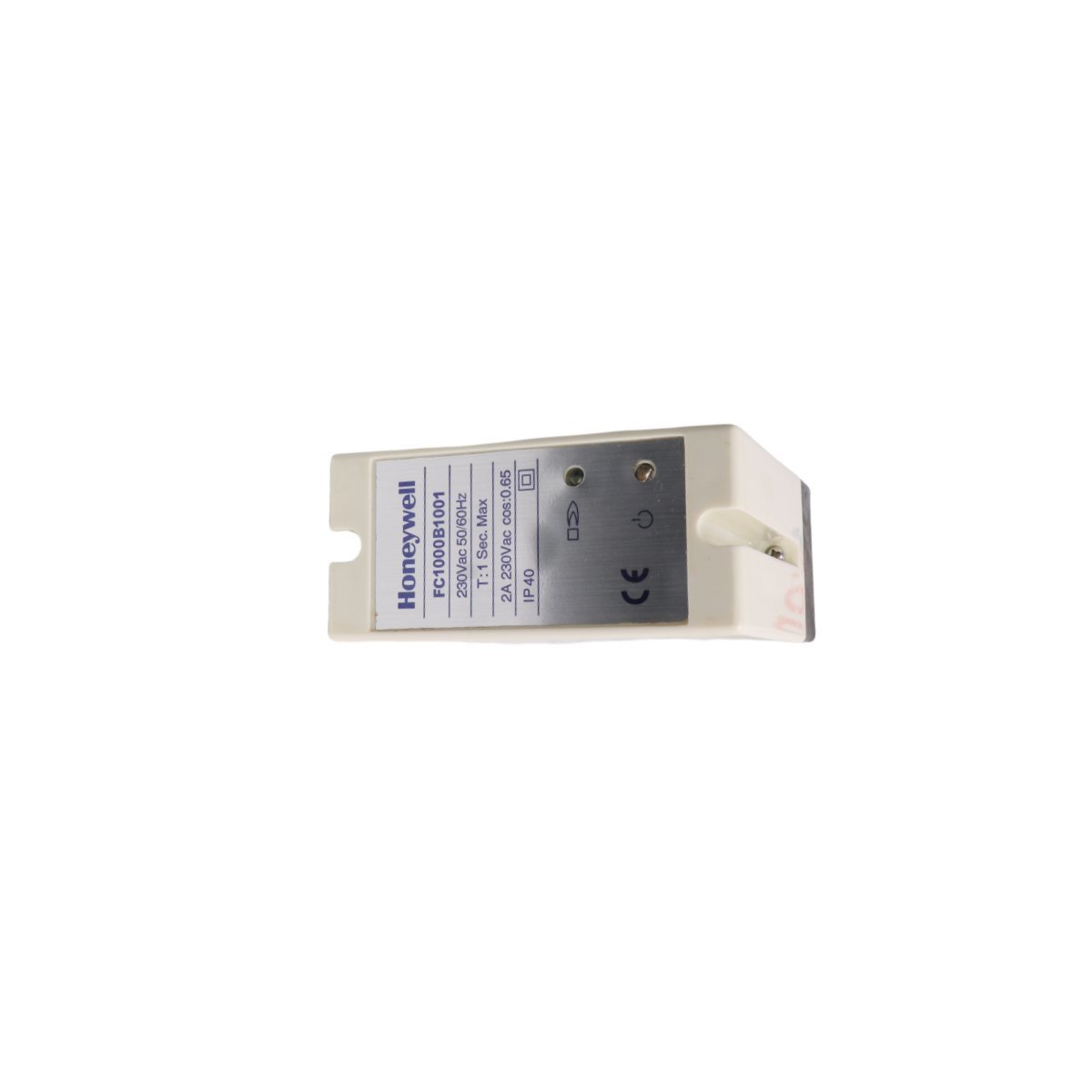
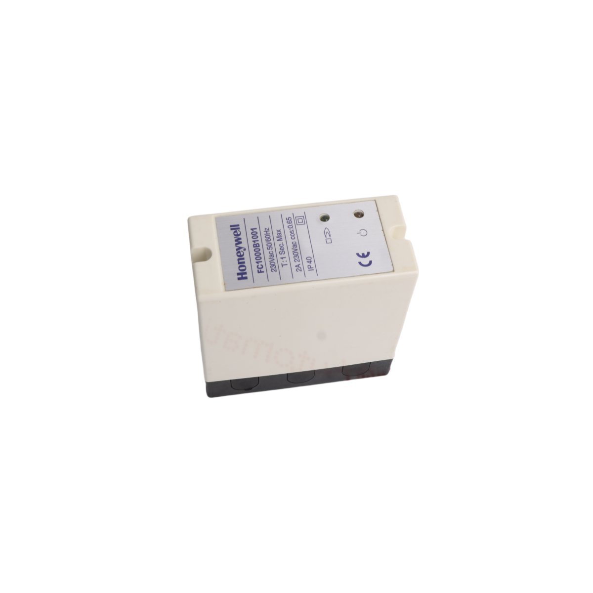
The Honeywell FC1000B1001, also cataloged as the FC1000B1001 Flame Combustion Controller, operates as a dedicated hardware component for flame signal evaluation and burner safety trip execution within safety system platforms. The controller processes ultraviolet or optical flame sensor inputs directly, continuously validating flame presence against configured safety thresholds. When flame loss occurs, internal logic circuits interrupt fuel safety shutoff valve outputs within milliseconds to enforce a fail-safe state across the burner management loop.
Hardware Specifications
Parameter
Specification
Model
FC1000B1001
Brand
Honeywell
Origin
USA
Weight
0.42 kg
Dimensions
11.5 x 11.0 x 5.2 cm
Operating Temp
-20 to 60 deg C
Power Consumption
24 VDC (4.5 W Nominal)
Product Series
Safety System Series
Module Type
Flame Combustion Controller
Signal Input Type
Flame Scanner Signal / 4-20 mA HART Loop
Response Time
Less than 1.0 s (Flame Failure Response)
Channel Isolation and HART Loop Integration
The module incorporates channel-to-channel isolation circuits alongside 4-20 mA HART loop protocol processing to prevent electrical noise from corrupting flame intensity telemetry. Internal galvanic barriers separate high-voltage ignition interference from low-voltage logic buses, because spark igniters generate severe electromagnetic transients during start-up sequences. Furthermore, onboard signal filters smooth out minor flame flicker variations, whereas true flame loss immediately triggers safety relay opening to guarantee prompt fuel cut-off execution.
Frequently Asked Questions
Q: Does the FC1000B1001 controller permit hot-swapping during active burner operation?
A: Maintenance personnel must shut down the associated burner loop and disconnect main supply power before module extraction, because pulling an active flame card forces an immediate emergency safety trip.
Q: How does the controller respond to flame scanner wiring short circuits?
A: Internal diagnostic circuits detect abnormal signal impedance instantly, drive internal alarm bits high, and transition the output relays into a de-energized fail-safe state.
Field Installation Guidelines
Mount the controller housing onto a standard DIN rail inside an IP54-rated metal enclosure. Ensure at least 45 mm of vertical clearance above and below the housing, because adequate natural air convection prevents thermal buildup within the internal power components. Connect field flame scanner leads using twisted-shielded cable pairs, and ground the braid shield at the cabinet main earth bar only. Tighten screw terminal connections to 0.5 Nm, while routing high-voltage ignition transformer lines through a separate cable duct to prevent cross-talk into sensitive flame monitoring channels.
Weight
0.42 kg
Country of Origin
USA
Dimension
11.5 x 11 x 5.2cm
Reviews
There are no reviews yet.
Be the first to review “Honeywell FC1000B1001 Safety System Flame Combustion Controller” Cancel reply



Reviews
There are no reviews yet.