
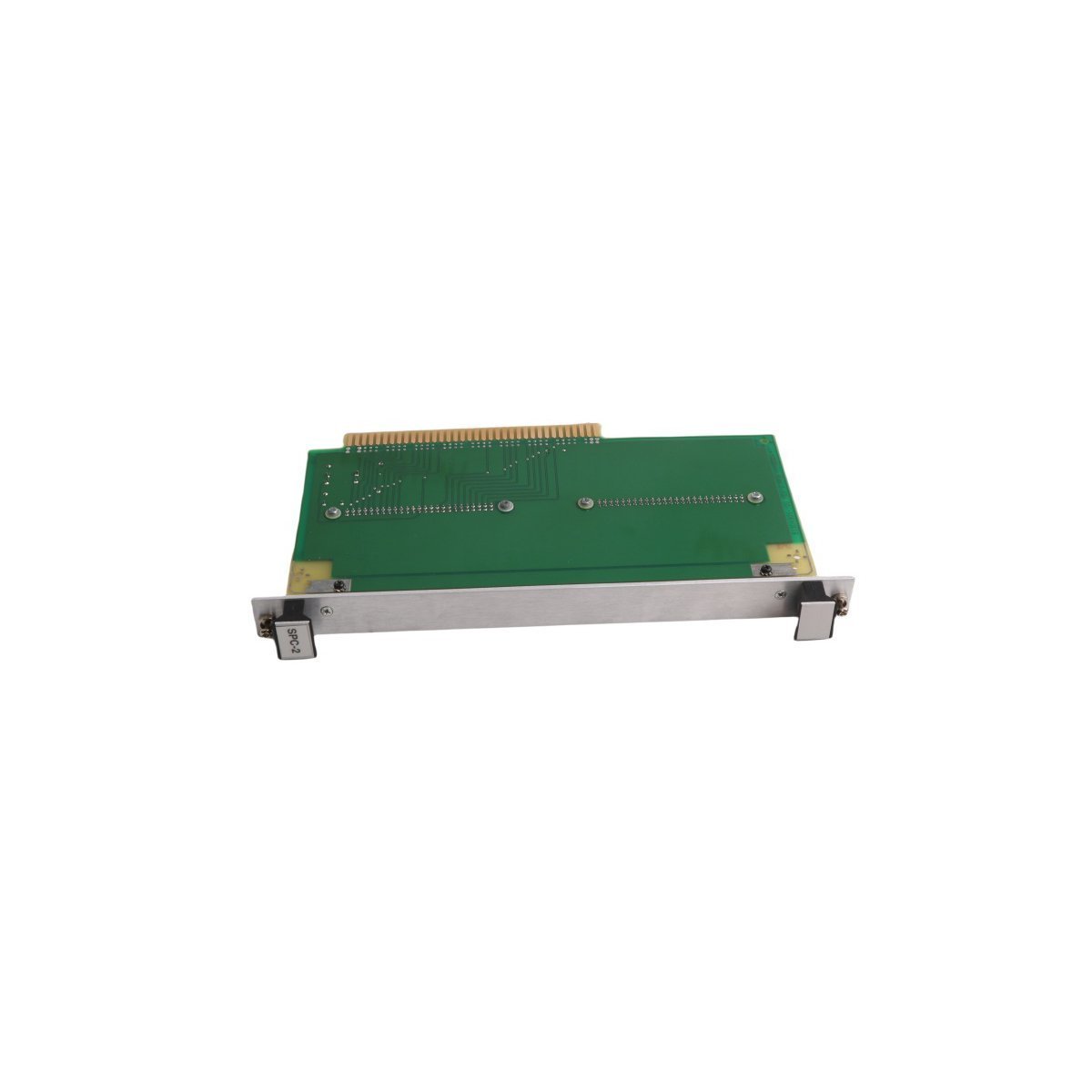
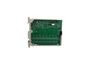
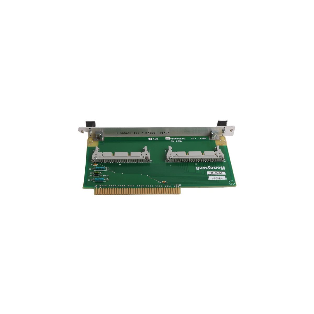
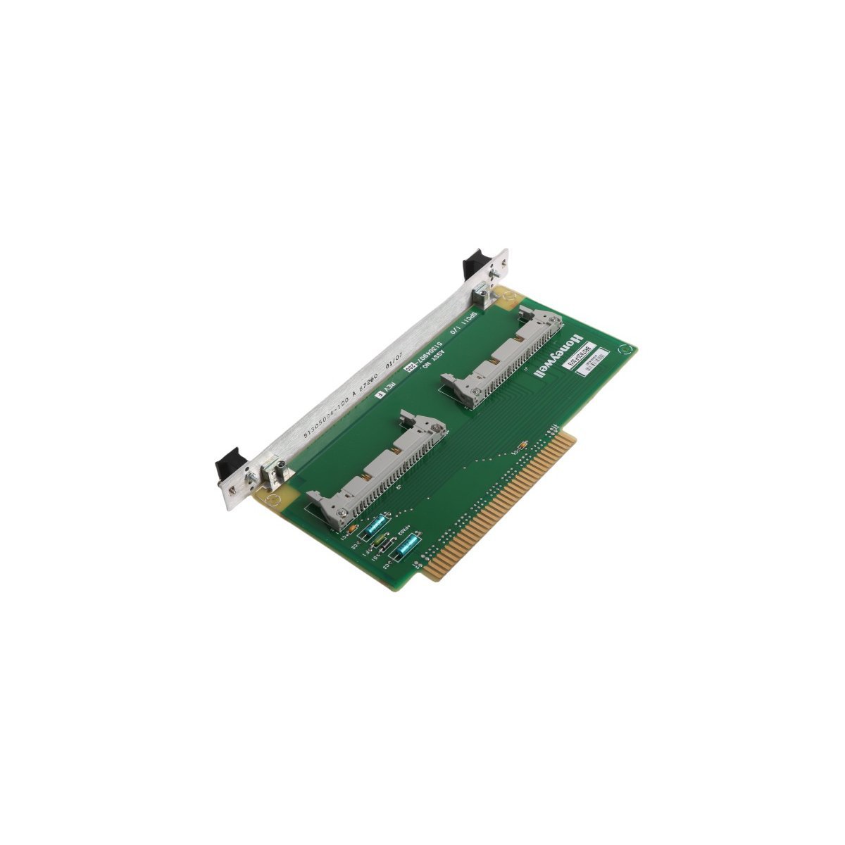
Honeywell 51304831-100 TDC 3000 Series I/O Board Input Output Card
Sale!Purchase the Brand New 51304831-100 Honeywell TDC 3000 Series I/O Board. Original Stock available for immediate Global Shipping. View full technical specifications and installation details.
99 in stock


- Power Isolation & ESD Safety: Turn off cabinet rack power completely before inserting the card, and wear an ESD wrist strap fastened to an unpainted chassis point.
- Mechanical Slot Insertion: Slide the card along the chassis guide rails, and push evenly on both ejector levers until the backplane connector mates securely.
- Shielding & Wiring Routing: Connect all field cable drain wires to the central grounding bar, and route communication lines away from high-voltage power conduits with at least 30 cm clearance.
- Connector Tightening: Tighten all terminal block retaining screws firmly, and check that threaded conduit connections engage at least five full threads before applying system power.
- Commissioning Inspection: Check all terminal wiring pinouts against field loop diagrams, and clear cabinet dust before restoring bus power to the rack frame.
Honeywell 51304831-100 TDC 3000 Series I/O Board
The Honeywell 51304831-100, also cataloged as the 51304831-100 I/O Board, operates as a dedicated hardware component for field signal acquisition and control command execution within TDC 3000 Series platforms.
Hardware Specifications
| Parameter | Specification |
|---|---|
| Model | 51304831-100 |
| Brand | Honeywell |
| Origin | USA |
| Weight | 0.18 kg |
| Dimensions | 22.3 x 14.0 x 1.5 cm |
| Operating Temp | Standard industrial limits (0 to +60 deg C baseline) |
| Power Consumption | Standard backplane power draw |
| Module Type | I/O Board (TPDG) |
| Network/System | TDC 3000 Series DCS |
| Communication Service | Ethernet router interface routing |
| HS Code | 8537101190 |
| Lifecycle Status | Active |
Process Control & DCS Signal Integration
This interface board processes analog and digital signals directly across field transmitter loops and final control elements. Internal optocouplers isolate field-side transients from the sensitive backplane logic, whereas channel-to-channel isolation prevents electrical cross-talk during continuous multi-loop operation. Integrated signal-conditioning circuitry filters electromagnetic noise, and onboard digital converters transmit clean process values over the system bus. Furthermore, dedicated diagnostic hardware continuously monitors signal path integrity, while routing nodes route telemetry data to central controller processors with minimal transmission latencies.
Frequently Asked Questions
Q: How do field technicians verify backplane communication and signal health during operation?
A: Status indicators on the board surface display live bus traffic and fault conditions directly, so technicians isolate channel anomalies without interrupting neighboring loop operations.
Q: What grounding precautions prevent signal degradation across mixed analog and digital wiring?
A: Technicians must terminate overall cable shields at a single low-impedance ground bus bar because multiple grounding points create stray circulating currents and introduce noise into field measurements.
Q: How does channel-to-channel isolation protect the system during field-side electrical faults?
A: Galvanic barriers isolate each input/output pathway, so high-voltage surges or accidental short circuits remain localized to a single channel without damaging backplane circuitry or adjacent process loops.
Field Installation Guidelines
| Weight | 0.18 kg |
|---|---|
| Country of Origin | USA |
| Dimension | 22.3 x 14 x 1.5cm |


Reviews
There are no reviews yet.