
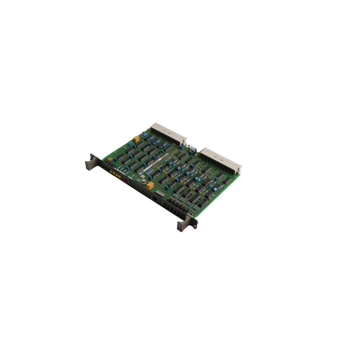
ABB HIEE401091R0002 GD9924 BE V2 UNITROL Drive Control Board
Sale!Buy brand new ABB HIEE401091R0002 GD9924 BE V2 drive control boards with original stock and fast global shipping. High-reliability DCS excitation controller card.
99 in stock


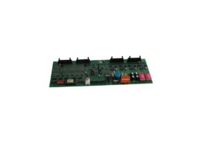
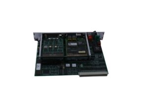
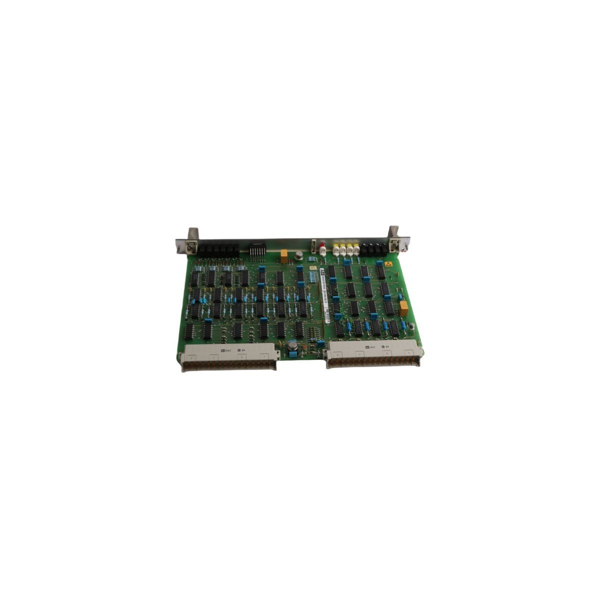
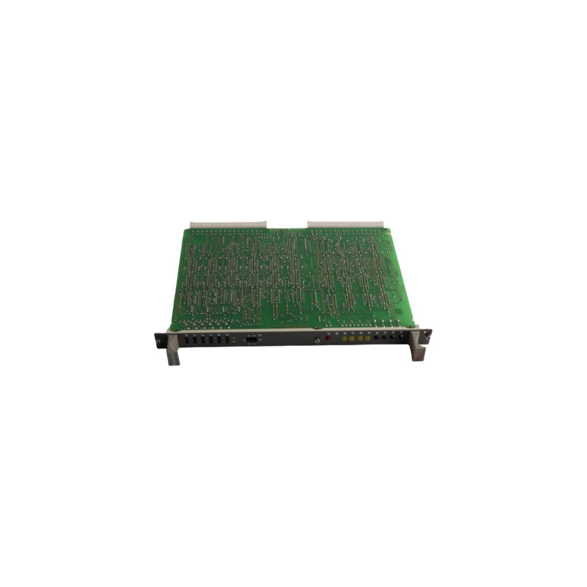
ABB HIEE401091R0002 GD9924 BE V2 Drive Control Board
Configured for pulse firing execution and fast regulation in UNITROL Excitation Systems, the ABB HIEE401091R0002 GD9924 BE V2 (HIEE401091R0002 GD9924 BE Drive Control Board) provides direct physical/electrical execution. Engineers seat this controller assembly directly into rack sub-planes, where processing nodes calculate phase angles and output gating pulses to heavy thyristor bridges. Built with internal bus interfaces and high-speed processing circuits, the board reduces system latency while it maintains synchronization across excitation loops.
Hardware Specifications
| Parameter | Specification |
|---|---|
| Model | HIEE401091R0002 GD9924 BE V2 |
| Brand | ABB |
| Origin | Sweden |
| Weight | 0.30 kg |
| Dimensions | 2.0 x 19.7 x 26.1 cm |
| Operating Temp | Standard Industrial Grade |
| Power Consumption | Optimized Power Rail Standard |
| Board Type | Drive Control Board |
| Product Family | UNITROL Excitation Systems |
| System Classification | DCS / Excitation Control |
| HS Code | 8537101190 |
Backplane Bus Communication Velocity and Firmware Compatibility
The control board utilizes high-speed backplane bus lines, so processor nodes transmit switching commands without introducing loop delays. Integrated firmware flashing routines verify board compatibility prior to initialization, which prevents firmware mismatch errors across redundant processor configurations. Furthermore, hardware handshake logic continuously coordinates data transfers with adjacent system cards, whereas dedicated diagnostic routines monitor bus health to eliminate data dropouts during heavy network traffic.
Frequently Asked Questions
Q: How do field technicians verify firmware flash compatibility prior to board replacement?
A: System operators poll the card revision through the supervisory network terminal. The internal EEPROM returns the active firmware build string, whereupon field engineers match the revision tag against the system controller profile before applying bus power.
Q: What precautions prevent signal jitter across the drive control outputs?
A: Engineers must ground all ribbon cable shielding at the sub-rack card cage chassis. Consequently, low-impedance ground planes route stray high-frequency transients away from sensitive gate-drive logic traces.
Q: Can maintenance staff extract the board while the sub-rack remains energized?
A: Technicians must isolate main power supplies and disable thyristor bridge firing loops before board removal. Hot-swapping without isolating gate-drive outputs risks unintended gating signals and triggers overcurrent trips across the power section.
Field Installation Guidelines
Technicians must install the board within clean, ESD-shielded enclosures that comply with standard industrial IP rating guidelines. Align the PCB guide rails carefully with the rack enclosure slots, and then push the unit firmly until the rear backplane connectors seat completely into the mating socket. Secure the front panel retention screws using a calibrated torque tool, applying no more than 0.5 Nm of force to prevent thread stripping.
Route all external firing pulse leads and communication lines separately from high-voltage AC cables. Maintain a clear separation distance of at least 200 mm between control wiring and main drive power buses to prevent electromagnetic interference. Before re-energizing the sub-rack assembly, inspect grounding straps at the cabinet earth rail, while verifying that 360-degree shield clamps ground all Ethernet and communication conduits.
| Weight | 1 kg |
|---|---|
| Country of Origin | Sweden |
| Dimension | 2 x 19.7 x 26.1 cm |
Reviews
There are no reviews yet.