
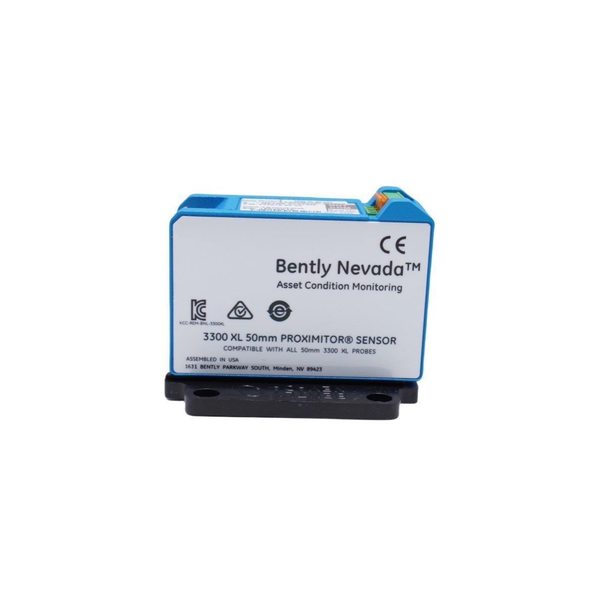
Bently Nevada 330878-91-00 3300 XL 50mm Proximitor Sensor
Sale!Order Bently Nevada 330878-91-00 3300 XL 50 mm Proximitor Sensor. Brand New condition, Original Stock guaranteed with Global Shipping for turbine condition monitoring systems.
99 in stock


Bently Nevada 330878-91-00 3300 XL 50 mm Proximitor Sensor
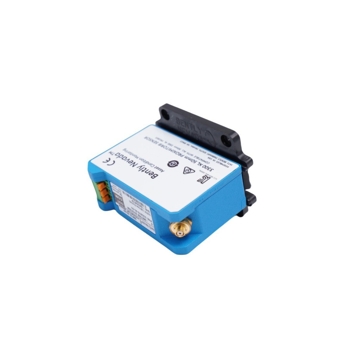
The Bently Nevada 330878-91-00, also cataloged as the 330878 Proximitor Sensor, operates as a dedicated hardware component for extended linear range axial displacement and rotor expansion measurement within TSI platforms. The module conditions raw eddy-current signal changes into proportional DC and AC voltage outputs, which allows downstream monitoring racks to capture differential expansion across large rotating machinery.
Suffix Breakdown & Model Matrix
| Option Code | Configuration Parameter | Specification Value |
|---|---|---|
| 330878 | Base Model | 3300 XL 50 mm Proximitor Sensor |
| -91 | System Length & Mounting | 19.0 meter (62.3 feet) total system length, DIN-rail mount |
| -00 | Agency Approval Option | No approvals |
Hardware Specifications
| Parameter | Specification |
|---|---|
| Model | 330878-91-00 |
| Brand | Bently Nevada |
| Origin | USA |
| Weight | 1.48 kg |
| Dimensions | 28 x 26 x 6 cm |
| Operating Temp | -35 deg C to +65 deg C |
| Power Consumption | External supply, -24 VDC nominal (-17.5 VDC to -26 VDC) |
| Linear Range | 27.9 mm (1100 mils) |
| System Length | 19.0 meter |
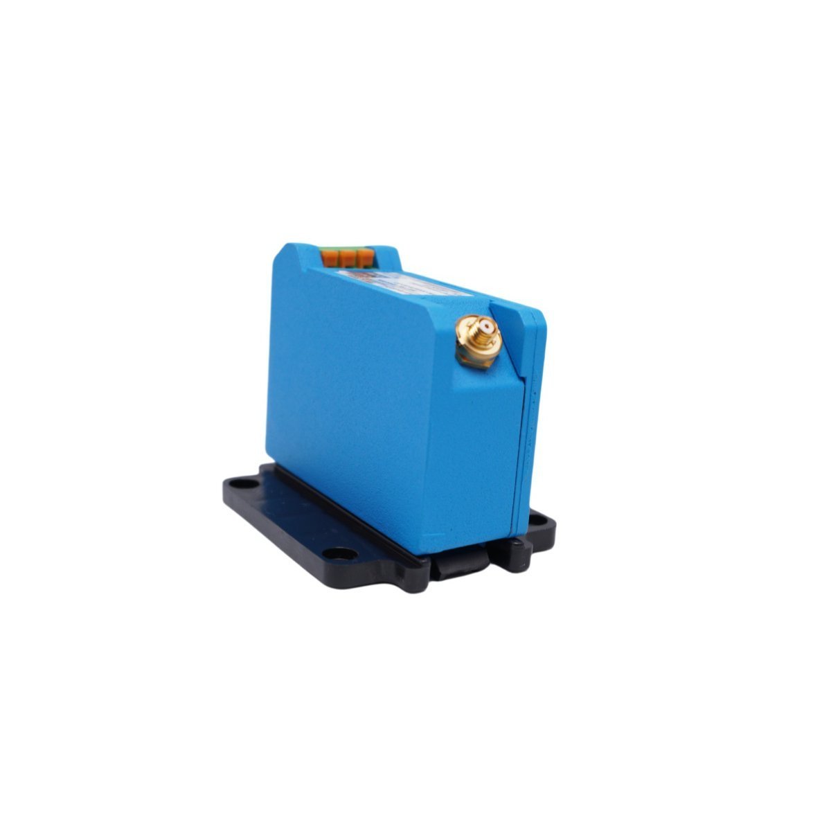
| Mounting | 35 mm DIN-rail mount |
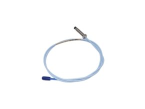
| Transducer Compatibility | 3300 XL 50 mm proximity probe and matched extension cable |
Machinery Monitoring & Eddy-Current Probe Mechanics
Engineers utilize precise eddy-current probe scaling to process signals over the 27.9 mm dynamic measurement span. During physical commissioning, field technicians execute gap voltage validation (-10 VDC targets) by adjusting the 50 mm probe physical placement until the signal conditioning circuitry outputs -10.0 VDC. This calibration places the shaft target surface at the exact electrical center of the extended measurement linear range.
Because structural thermal growth shifts component alignment during operation, the sensor tracks continuous rotor dynamics and turbine casing differential expansion without making physical contact. Furthermore, field installers maintain required physical spacing between adjacent large-diameter sensor heads inside the machine housing, which guarantees effective cross-talk suppression and prevents mutual inductive coupling between channels.
Frequently Asked Questions
Q: Why must field technicians maintain the complete 19.0-meter system length during installation?
A: The Proximitor Sensor internal oscillator relies on a tuned electrical inductance loop. Consequently, trimming or extending the matching probe cable alters total loop resistance, which degrades signal linear range accuracy and invalidates factory calibration.
Q: How does the unit process raw eddy-current signals into usable monitoring signals?
A: The internal circuit generates a high-frequency excitation signal that drives the probe tip coil. As the conductive target moves relative to the probe face, eddy-current losses shift the oscillation amplitude, and the Proximitor demodulates this change into a proportional voltage output.
Q: What power rail specification does the sensor require for operation?
A: The sensor draws power from a regulated -24 VDC external supply rail. Field wiring connects through screw terminal blocks while maintaining direct signal isolation from local ground chassis references.
Field Installation Guidelines
Installers execute physical mounting by snapping the housing onto a standard 35 mm DIN rail inside a protective weather-tight enclosure. Because clean earth connections prevent signal degradation, technicians connect the dedicated shield drain wire directly to local instrumentation earth ground.
Connect a digital multimeter to the raw signal buffer terminals on the front panel. While observing the meter output reading, adjust the physical position of the 50 mm probe head relative to the shaft surface; stop movement immediately when the multimeter registers the target gap voltage validation reading of -10.0 VDC.
Tighten all mechanical locknuts to fix the probe position securely. Route the matching 19.0-meter extension cable along metal conduit trays, and maintain a minimum bend radius of 75 mm to prevent core wire fatigue. Finally, verify that all signal wiring runs maintain physical separation from high-voltage motor power leads so that electromagnetic interference does not corrupt low-level voltage signals.
| Weight | 1.48 kg |
|---|---|
| Country of Origin | USA |
| Dimension | 28 x 26 x 6cm |




Reviews
There are no reviews yet.