
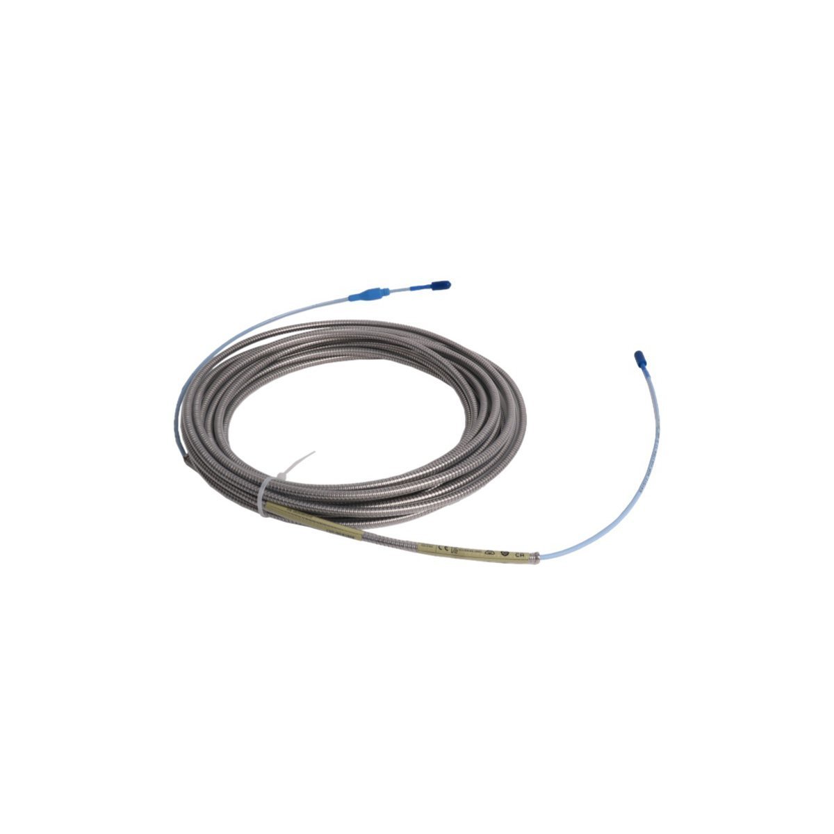
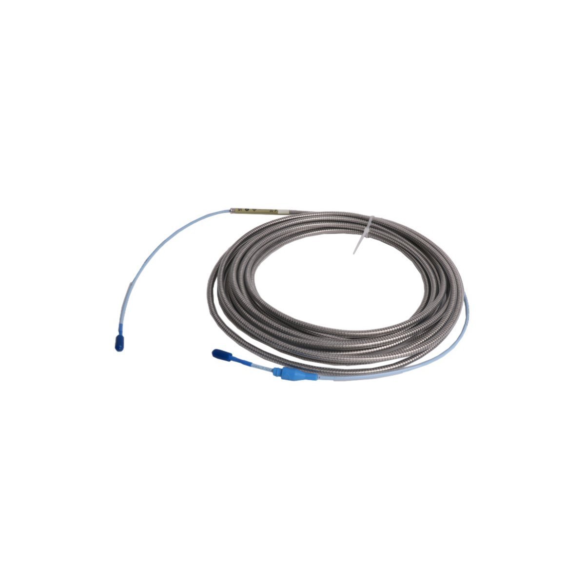
330130-065-00-05 Bently Nevada 3300 XL Extension Cables Transducer
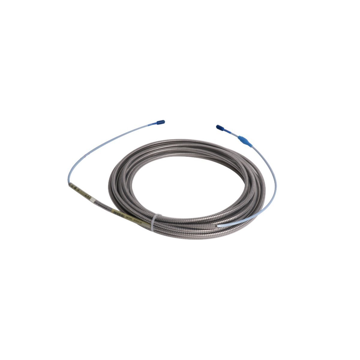
Sale!Buy the Bently Nevada 330130-065-00-05 3300 XL 6.5m Extension Cable. Brand New item in Original Stock with Global Shipping. Features 330 N pull strength and ATEX approvals.
99 in stock


Bently Nevada 330130-065-00-05 3300 XL Extension Cable
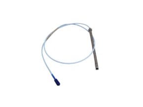
Configured for high-frequency signal transmission between proximity probes and Proximitor sensors in TSI platforms, the Bently Nevada 330130-065-00-05 (330130 Extension Cables) provides direct electrical execution. Technicians interlock this 6.5-meter coaxial cable assembly within proximity transducer loops to relay physical gap change signals without frequency attenuation. The physical construction incorporates a patented CableLoc jacket coupling, gold-plated ClickLoc connectors, and multi-agency explosion-proof ratings for continuous duty in demanding machinery monitoring environments.
Suffix Breakdown & Model Matrix
| Option Segment | Value | Specification Description |
|---|---|---|
| Cable Length Option | 065 | 6.5 meters (21.3 feet) cable length |
| Connector Armor Option | 00 | Standard cable without stainless steel armor |
| Agency Approval Option | 05 | Multiple approvals (CSA, ATEX, IECEx) |
Hardware Specifications
| Parameter | Specification |
|---|---|
| Model | 330130-065-00-05 |
| Brand | Bently Nevada |
| Origin | USA |
| Weight | 0.06 kg |
| Dimensions | 1.8 x 1.6 x 123 cm |
| Operating Temp | Standard operating range up to 177 deg C |
| Power Consumption | Passive signal conductor (zero power dissipation) |
| Cable Length | 6.5 meters (21.3 feet) |
| Mechanical Pull Strength | 330 N (75 lbf) via CableLoc design |
| Connector Type | Gold-plated ClickLoc miniature coaxial connectors |
| System Compatibility | 3300 XL 8 mm and 5 mm Proximity Transducer Systems |
| HS Code | 8537101190 |
Eddy-Current Probe Scaling and Signal Transmission
The cable maintains precise loop impedance across its 6.5-meter span, enabling accurate eddy-current probe scaling at the Proximitor sensor terminal stage. Furthermore, the constant characteristic impedance minimizes voltage drop and phase shift as target movement modifies the magnetic field at the probe tip. Field engineers perform gap voltage validation (-10 VDC target at nominal operational center) to confirm loop tuning after installing the extension cable. Consequently, the low-capacitance dielectric prevents cross-talk suppression failures between adjacent channels while accurately conveying high-frequency dynamic responses generated by complex rotor dynamics.
Frequently Asked Questions
Q: How does the ClickLoc connector prevent accidental signal interruption during high-vibration operation? A: The gold-plated ClickLoc connector utilizes an internal tactile latch mechanism. Consequently, technicians snap the coaxial halves together until they feel and hear an audible click, which guarantees electrical contact stability and resists vibration-induced back-off.
Q: Does this extension cable allow routing through oil-filled bearing housings without fluid migration? A: Yes, because the inner assembly integrates a specialized FluidLoc seal option, it prevents lubricating oil and industrial fluids from wicking through the internal conductor strands into outer junction boxes.
Q: What impact does altering the overall extension cable length have on 3300 XL system calibration? A: The total electrical length of the probe and extension cable combined must match the design rating (typically 5 meters, 7 meters, or 9 meters) of the paired Proximitor Sensor. Changing cable length without retuning alters system capacitance, which directly shifts the voltage scaling output.
Field Installation Guidelines
Technicians must observe strict mechanical handling procedures during cable placement. First, inspect the male and female ClickLoc interfaces to verify that no oil, dust, or metal shavings rest on the gold-plated pins. Align the connector ends carefully, then push them together until the locking collar clicks securely into position.
Next, slip the connector protector sleeve over the mated junction and twist it shut to isolate the signal line from physical contamination and stray grounding. Route the cable through dedicated metallic conduit or cable trays, taking care to maintain a minimum bend radius of 25.4 mm (1.0 in) to prevent internal dielectric damage. Anchor the cable at regular intervals so that tension remains well below the 330 N (75 lbf) CableLoc pull limit. Finally, ground the overall system shield braid at the main monitor rack terminal while leaving the field probe end floating, which prevents earth potential differences from creating ground loops across the TSI signal path.
| Weight | 0.06 kg |
|---|---|
| Country of Origin | USA |
| Dimension | 1.8 x 1.6 x 123cm |


Reviews
There are no reviews yet.