
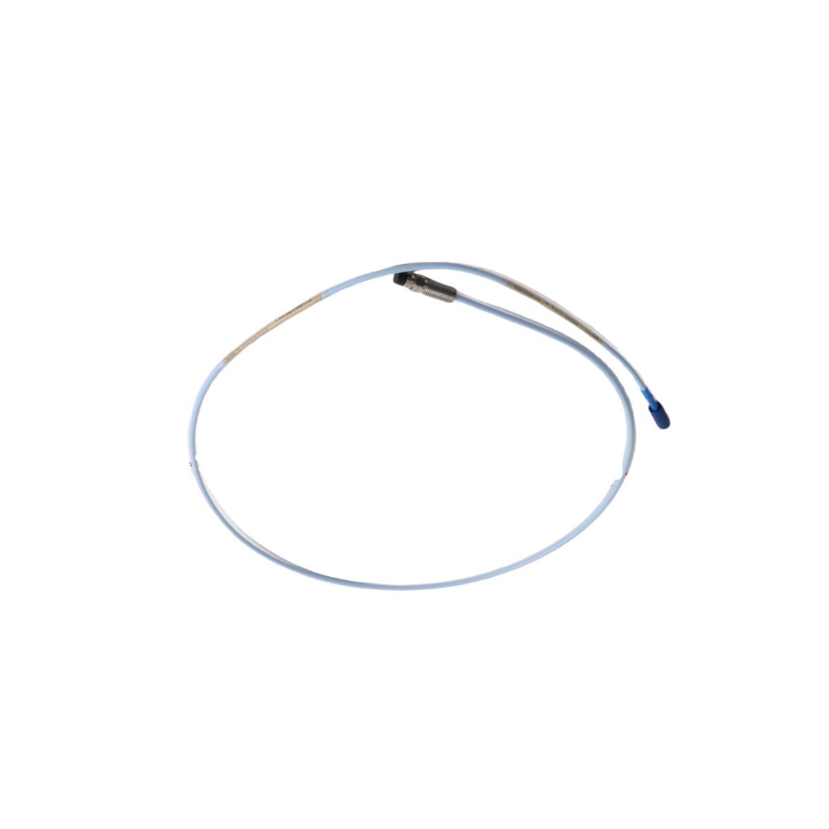
Bently Nevada 330106-05-30-10-02-05 3300 XL Proximity Probe Sensors
Sale!Order the Bently Nevada 330106-05-30-10-02-05 3300 XL Reverse Mount Probe. Brand New condition, Original Stock guaranteed with Global Shipping for TSI machinery monitoring systems.
99 in stock


Bently Nevada 330106-05-30-10-02-05 3300 XL Reverse Mount Proximity Probe
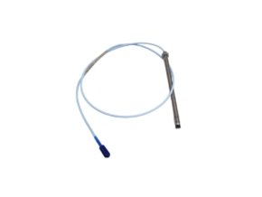
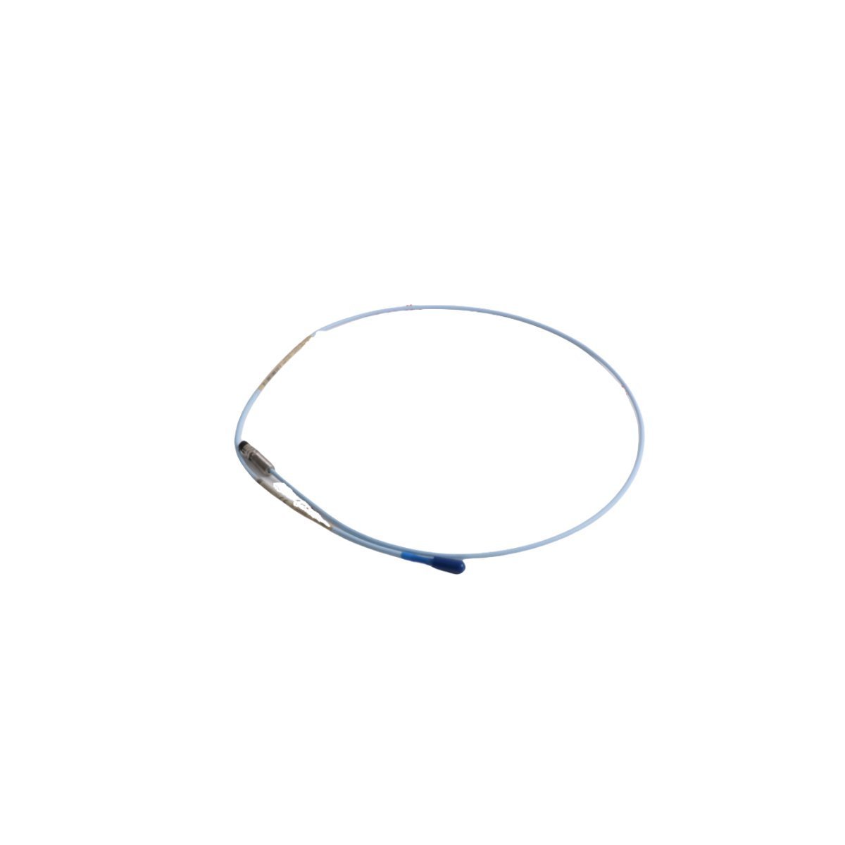
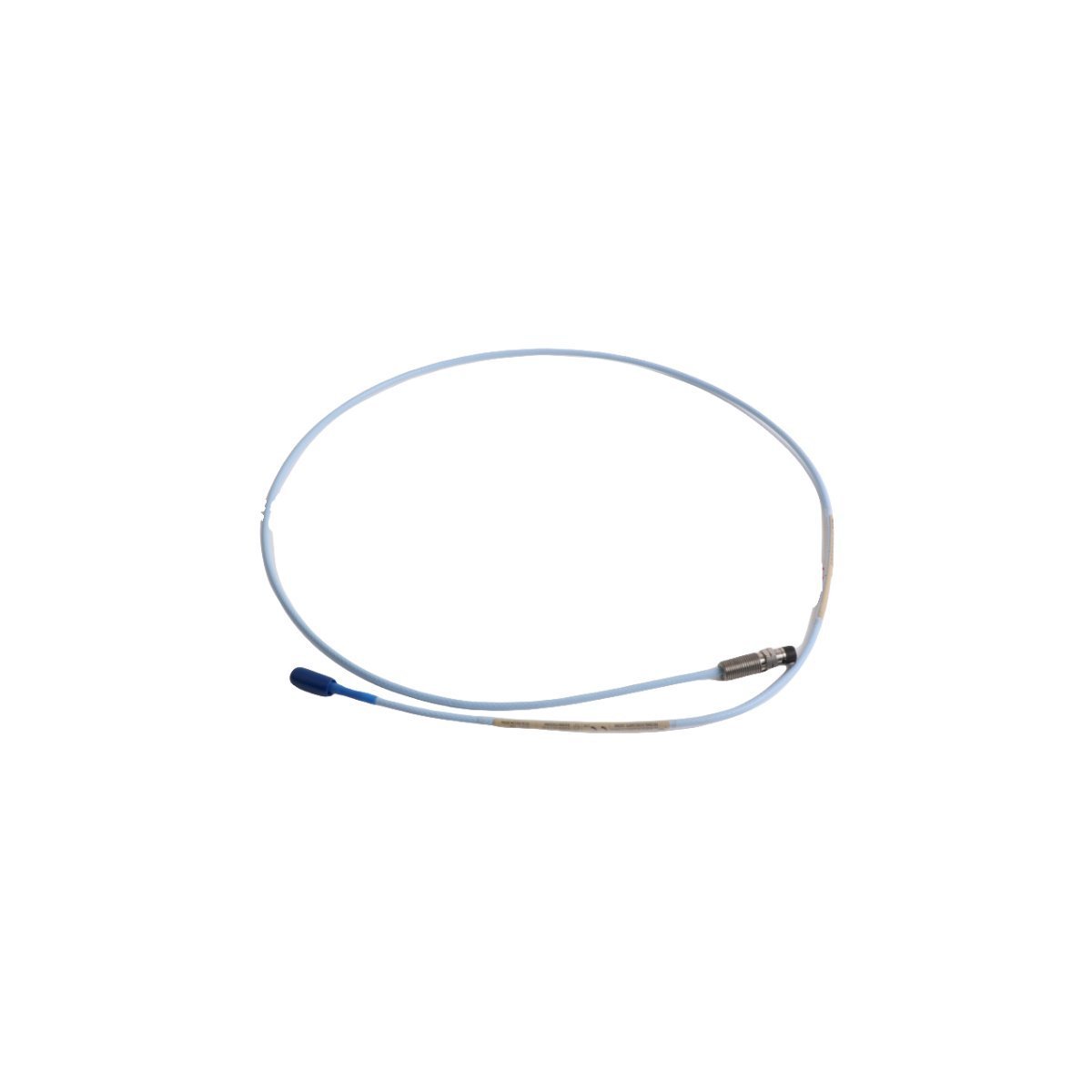
The Bently Nevada 330106-05-30-10-02-05, also cataloged as the 330106 Reverse Mount Proximity Probe, operates as a dedicated hardware component for contactless shaft displacement and dynamic vibration measurement within TSI platforms. The probe head tip radiates a continuous high-frequency electromagnetic field directly onto the rotating shaft target, while the companion Proximitor Sensor converts target gap fluctuations into linear DC voltage and AC dynamic signals.
Suffix Breakdown & Model Matrix
| Option Code | Configuration Parameter | Specification Value |
|---|---|---|
| 330106 | Base Model | 3300 XL 8 mm Reverse Mount Proximity Probe, 3/8-24 UNF thread |
| -05 | Unthreaded Length Option | 0.5 in (13 mm) |
| -30 | Overall Case Length Option | 3.0 in (76 mm) |
| -10 | Total Length Option | 1.0 meter (3.3 feet) |
| -02 | Connector Option | Miniature coaxial ClickLoc connector with connector protector |
| -05 | Agency Approval Option | Multiple Approvals (CSA, ATEX, IECEx) |
Hardware Specifications
| Parameter | Specification |
|---|---|
| Model | 330106-05-30-10-02-05 |
| Brand | Bently Nevada |
| Origin | USA |
| Weight | 0.06 kg |
| Dimensions | 1.0 x 0.8 x 113 cm |
| Operating Temp | -51 deg C to +177 deg C |
| Power Consumption | External excitation via Proximitor Sensor (-24 VDC rail) |
| Linear Range | 2.0 mm (80 mils) |
| Target Material | AISI 4140 steel (standard factory calibration) |
| Connector Type | ClickLoc miniature coaxial with protective boot |
| Certifications | CSA, ATEX, IECEx hazardous area approvals |
Machinery Monitoring & Eddy-Current Probe Mechanics
Engineers execute precise eddy-current probe scaling to ensure predictable signal linear voltage translation across the 80 mil sensing span. During physical mounting setup, installers verify gap voltage validation (-10 VDC targets) as they slowly rotate the probe body until the Proximitor voltage output reads -10.0 VDC. This adjustment places the shaft surface at the center of the dynamic measurement envelope.
Because physical motion changes the inductive field geometry, the transducer continuous processing tracks critical rotor dynamics across high-speed rotating machinery without surface contact. Moreover, field technicians maintain exact spatial clearance around adjacent sensor tips inside bearing housings, which guarantees effective cross-talk suppression and eliminates mutual inductive interference.
Frequently Asked Questions
Q: How does the reverse mount design alter physical probe installation compared to standard probes?
A: Technicians insert the probe body through the inside of the bearing housing sleeve or mounting bracket rather than threading it from the outside, which allows probe replacement without dismantling external conduit runs.
Q: How do installers verify target voltage setting before securing the outer locknut?
A: Technicians connect a multimeter across the raw buffer outputs of the Proximitor Sensor while they adjust physical probe depth. As soon as the reading stabilizes at the target gap voltage validation value of -10.0 VDC, the installer torques the jam nut to lock physical depth.
Q: What function does the ClickLoc connector protector serve in field junction boxes?
A: The insulating silicone sleeve seals the joined miniature coaxial connectors, which prevents signal contamination from moisture and eliminates ground loop noise by electrically isolating the coaxial outer shield from machine frame metal contact.
Field Installation Guidelines
Technicians install the reverse-mount body carefully so that they protect the PPS tip face from striking internal machine walls. Pull the integral 1.0-meter coaxial cable smoothly through the housing port, and thread the 3/8-24 UNF body into the internally threaded mounting bracket.
Attach a digital multimeter to the Proximitor Sensor output terminals to read raw loop bias voltage. Thread the probe body toward the target shaft while you observe the multimeter display; stop turning the probe body the moment the voltage reading reaches -10.0 VDC.
Tighten the locking jam nut against the bracket face so that you secure physical positioning. Route the coaxial cable along clean wire channels, and maintain a minimum bend radius of 25.4 mm (1.0 inch) so that you prevent internal shield damage. Push the ClickLoc coaxial connector firmly into the matching extension cable plug until the internal lock clicks, and then slide the silicone boot completely over the mating connection to isolate the signal ground from earth contact.
| Weight | 0.06 kg |
|---|---|
| Country of Origin | USA |
| Dimension | 1 x 0.8 x 113cm |


Reviews
There are no reviews yet.