
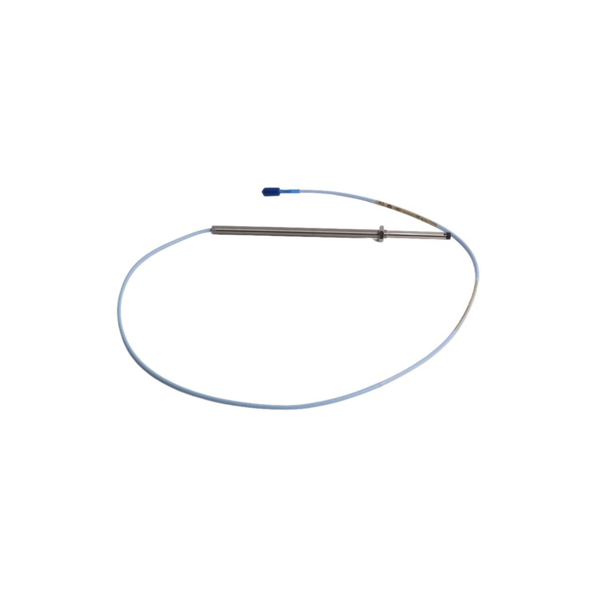
330103-06-15-10-12-05 Bently Nevada 3300 XL Proximity Sensors
Sale!Get brand new, original stock Bently Nevada 330103-06-15-10-12-05 3300 XL 8 mm proximity probes. We provide global shipping and full technical specs for your TSI systems.
99 in stock


Bently Nevada 330103-06-15-10-12-05 3300 XL 8 mm Proximity Probes
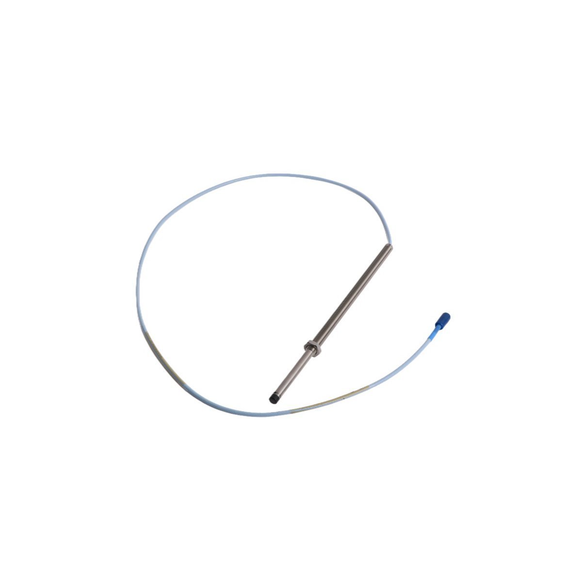
Configured for continuous shaft vibration and axial position measurements in TSI systems, the Bently Nevada 330103-06-15-10-12-05 (330103 3300 XL 8 mm Proximity Probe) provides direct physical signal acquisition for rotating machinery protection. This component converts mechanical displacement into high-frequency eddy-current impedance shifts, which the connected Proximitor Sensor conditions into proportional voltage outputs across the system backplane.
Suffix Breakdown & Model Matrix
| Option Code | Configuration Parameter | Specification Value |
|---|---|---|
| 330103 | Base Model | 3300 XL 8 mm Proximity Probe, M10x1 thread |
| -06 | Unthreaded Length Option | 60 mm unthreaded length |
| -15 | Overall Case Length Option | 150 mm overall case length |
| -10 | Total Length Option | 1.0 meter (3.3 feet) cable length |
| -12 | Connector Option | Miniature coaxial ClickLoc connector with cable protector |
| -05 | Agency Approval Option | Multiple Approvals (CSA, ATEX, IECEx) for hazardous areas |
Hardware Specifications
| Parameter | Specification |
|---|---|
| Model | 330103-06-15-10-12-05 |
| Brand | Bently Nevada |
| Origin | USA |
| Weight | 1.48 kg |
| Dimensions | 28 x 26 x 6 cm |
| Operating Temp | -51 deg C to +177 deg C |
| Power Consumption | Externally driven by Proximitor Sensor (-24 VDC system supply) |
| System Architecture | 3300 XL 8 mm Proximity Transducer System (API 670 compliant) |
| Thread Size | Metric M10x1 |
| Unthreaded Length | 60 mm |
| Case Length | 150 mm |
| Cable Length | 1.0 meter |
| Connector Type | Miniature coaxial ClickLoc connector |
| Hazardous Area Rating | CSA, ATEX, IECEx certified |
Machinery Monitoring & Eddy-Current Probe Mechanics
The probe relies on precise eddy-current probe scaling to convert target gap variation into physical voltage responses. Technicians execute gap voltage validation by adjusting the mechanical probe position until the raw signal reads a target output of -10 VDC during static calibration, which aligns the target directly in the center of the 80 mil (2.0 mm) linear range.
Because changes in target material alter electromagnetic reflection, engineers evaluate rotor dynamics by ensuring that the shaft material matches the probe factory calibration (AISI 4140 steel standard). Proper physical installation prevents signal cross-talk suppression issues when multiple probe tip heads operate in close physical proximity inside the bearing housing.
Frequently Asked Questions
Q: How do field engineers verify the correct mechanical installation gap before applying system power?
A: Installers thread the probe body toward the shaft target while observing a multimeter attached to the Proximitor Sensor output terminals. Adjust the probe depth until the DC gap voltage reaches -10.0 VDC (corresponding to roughly 1.0 mm or 40 mils of physical distance), and then secure the locking nut to lock the physical thread position.
Q: Does replacing a damaged 330103 probe require custom field calibration of the associated Proximitor Sensor?
A: Technicians can swap individual 3300 XL 8 mm components directly without recalibrating the system. Bently Nevada manufactures these probes to maintain total electrical interchangeability, provided that the combined probe, extension cable, and sensor match the designated 5.0 meter or 9.0 meter total system length.
Q: What precautions prevent signal noise and ground loops across the miniature ClickLoc connector joint?
A: Field personnel must install the coaxial ClickLoc connectors with clean, dry contacts and tighten them until the physical click engages. Additionally, technicians must insulate the connector connection from structural metal grounding by using the supplied translucent protective silicone sleeves.
Field Installation Guidelines
Technicians must maintain strict alignment during mechanical mounting to prevent thread binding and sensor face damage. Insert the probe tip into the tapped M10x1 machine casing hole, and hand-thread the probe body until the tip approaches the target shaft surface.
[ Target Shaft Surface ] | |<— Gap Distance (Target: -10 VDC / ~1.0 mm) | [ Probe Tip (8 mm) ] ===================== <– Threaded Case (M10x1) [ Locknut ] <– Torque to specs after setting voltageConnect a calibrated digital multimeter to the signal output terminals of the matching Proximitor Sensor. Rotate the probe body smoothly while monitoring the DC voltage signal. As the tip approaches the metal target, the voltage level drops from the open-air supply rail toward 0 VDC. Stop rotation precisely when the multimeter displays -10.0 VDC.
Tighten the probe locknut against the external machine casing to prevent vibrational drift. Next, route the integral 1.0 meter coaxial cable along dedicated instrumentation trays, avoiding proximity to high-voltage AC motor leads. Route the cable so that the bend radius never drops below 25.4 mm (1.0 inch). Finally, snap the ClickLoc coaxial connector firmly into the extension cable joint, and slide the flexible insulation sleeve over the junction to guarantee isolated signal transmission.
| Weight | 1.48 kg |
|---|---|
| Country of Origin | USA |
| Dimension | 28 x 26 x 6cm |




Reviews
There are no reviews yet.