
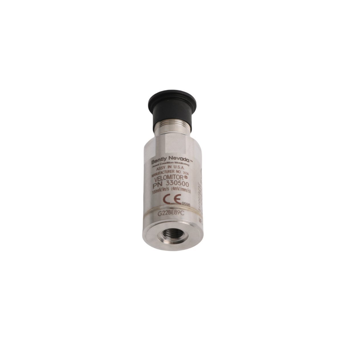
Bently Nevada 330500-00-00 Velomitor Piezo-velocity Vibration Sensor
Sale!Find complete technical data for the Bently Nevada 330500-00-00 Piezo-velocity sensor. Available as Brand New, Original Stock with fast Global Shipping.
99 in stock


- Mounting Surface Preparation: Machine the mounting location to a flat surface with a finish of 0.8 micrometers (32 microinches) or better. Tap the center hole to a minimum depth of 5 threads to ensure full engagement of the mounting stud.
- Torque Application Limits: Hand-thread the sensor onto the mounting stud until fully flush against the machine surface. Apply a calibrated torque wrench to the hex flats and tighten to exactly 4.5 N-m (40 in-lb) to prevent damage to the internal piezoelectric crystal crystal structure.
- Shield Grounding Protocol: Terminate the outer twisted-shielded cable pair braid strictly at the instrumentation rack common ground bus bar. Leave the shield floating and insulated at the sensor head to eliminate multi-point ground loops.
- Cable Strain Relief: Secure the signal cable within 150 mm (6 inches) of the sensor body using rigid clamps or conduit brackets to prevent cable whipping from introducing low-frequency strain noise into the velocity output.
Bently Nevada 330500-00-00 Velomitor Piezo-velocity Sensor
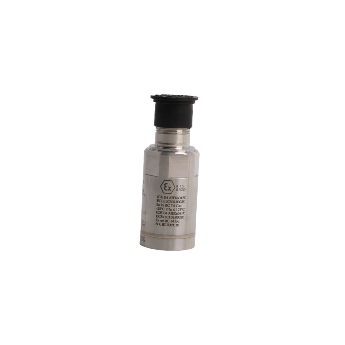
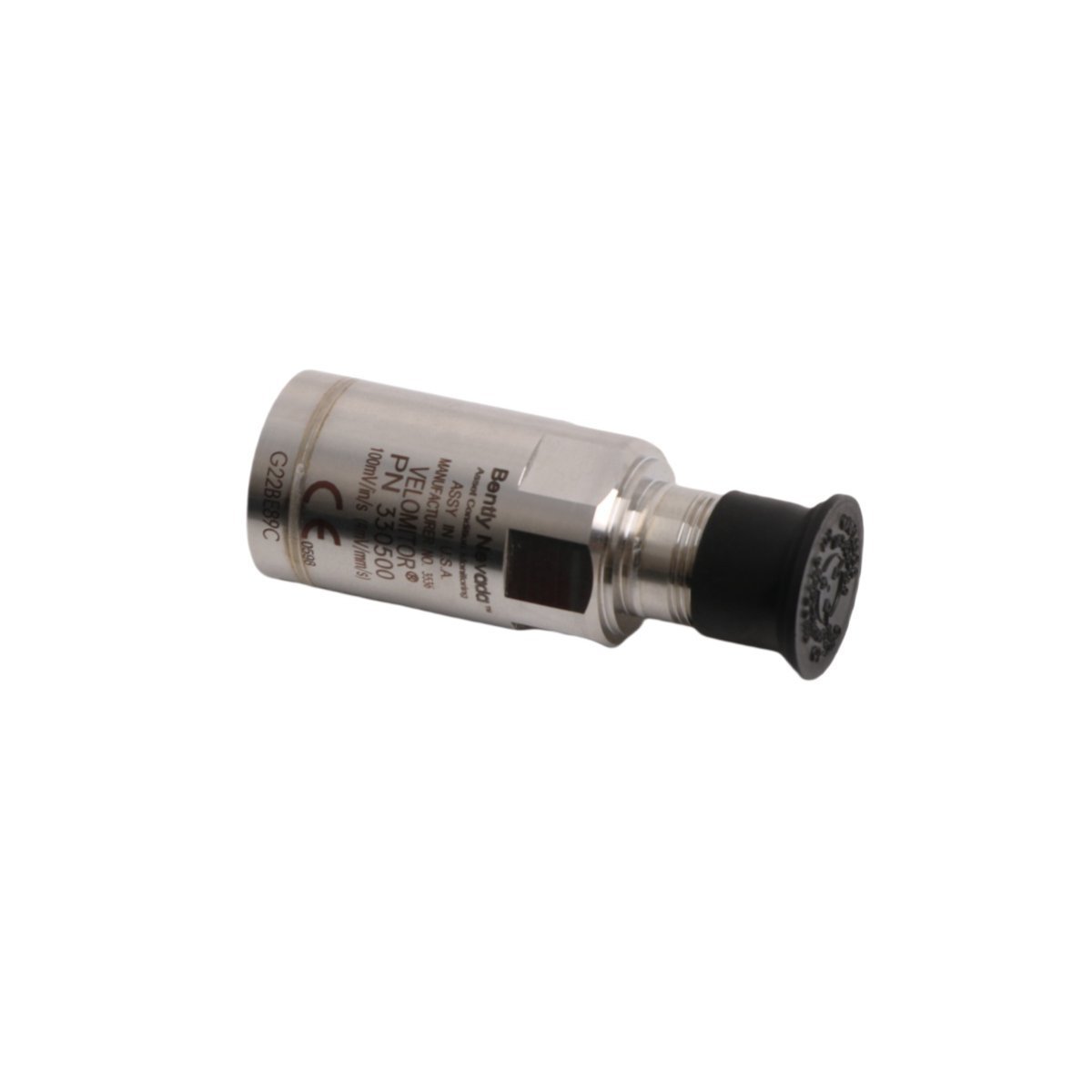
The Bently Nevada 330500-00-00, also cataloged as the 330500 Velomitor Piezo-velocity Sensor, operates as a dedicated hardware component for casing vibration monitoring within TSI platforms. The device utilizes internal piezoelectric crystals coupled with an integration circuit to measure absolute machinery casing velocity. It directly converts dynamic mechanical acceleration into a proportional voltage velocity signal, executing real-time machinery protection data routing to localized monitoring systems.
Hardware Specifications
| Parameter | Specification |
|---|---|
| Model | 330500-00-00 |
| Brand | Bently Nevada |
| Origin | USA |
| Weight | 0.16 kg |
| Dimensions | 2.5 x 2.5 x 7.2 cm |
| Operating Temp | -55 to +121 deg C |
| Power Consumption | 2 to 10 mA constant current |
| Sensitivity | 3.94 mV/mm/s (100 mV/in/s) +/-5% |
| Velocity Range | 1270 mm/s (50 in/s) peak |
| Amplitude Linearity | +/-2% up to 152 mm/s (6 in/s) peak |
| Output Bias Voltage | -12 +/-3.0 VDC |
| Dynamic Impedance | Less than 2400 ohm |
| Shock Survivability | 5000 g peak |
| Humidity Limit | 100% relative humidity (non-submerged) |
| Mounting Thread | 1/2-20 UNF standard |
| HS Code | 8537101190 |
Mechanical Monitoring & TSI Product Attributes
The sensor implements precise piezoelectric crystals rather than older eddy-current probe scaling to measure absolute structural housings. Technicians track operations through continuous bias voltage validation, evaluating the sensor condition across a stable -12 VDC target referenced to Pin A. The physical architecture isolates the internal circuitry from the external stainless steel shell, ensuring total case isolation to suppress electrical noise. This structural design blocks cross-talk suppression failures and mitigates base strain sensitivity variables to guarantee precise rotor dynamics data recording on high-speed industrial machinery casing.
Frequently Asked Questions
Q: How does a technician determine internal circuit health from the sensor bias voltage?
A: The operator measures the DC voltage output at the monitoring rack across the signal line. A steady reading within the -9 VDC to -15 VDC range confirms proper internal amplifier operation and cable integrity.
Q: Can the sensor withstand continuous exposure to moisture and harsh industrial environments?
A: Yes, the hermetically sealed housing provides IP67-grade environmental protection that tolerates up to 100% relative humidity, provided the connection point remains free from total liquid submersion.
Field Installation Guidelines
| Weight | 0.16 kg |
|---|---|
| Country of Origin | USA |
| Dimension | 2.5 x 2.5 x 7.2cm |



Reviews
There are no reviews yet.