
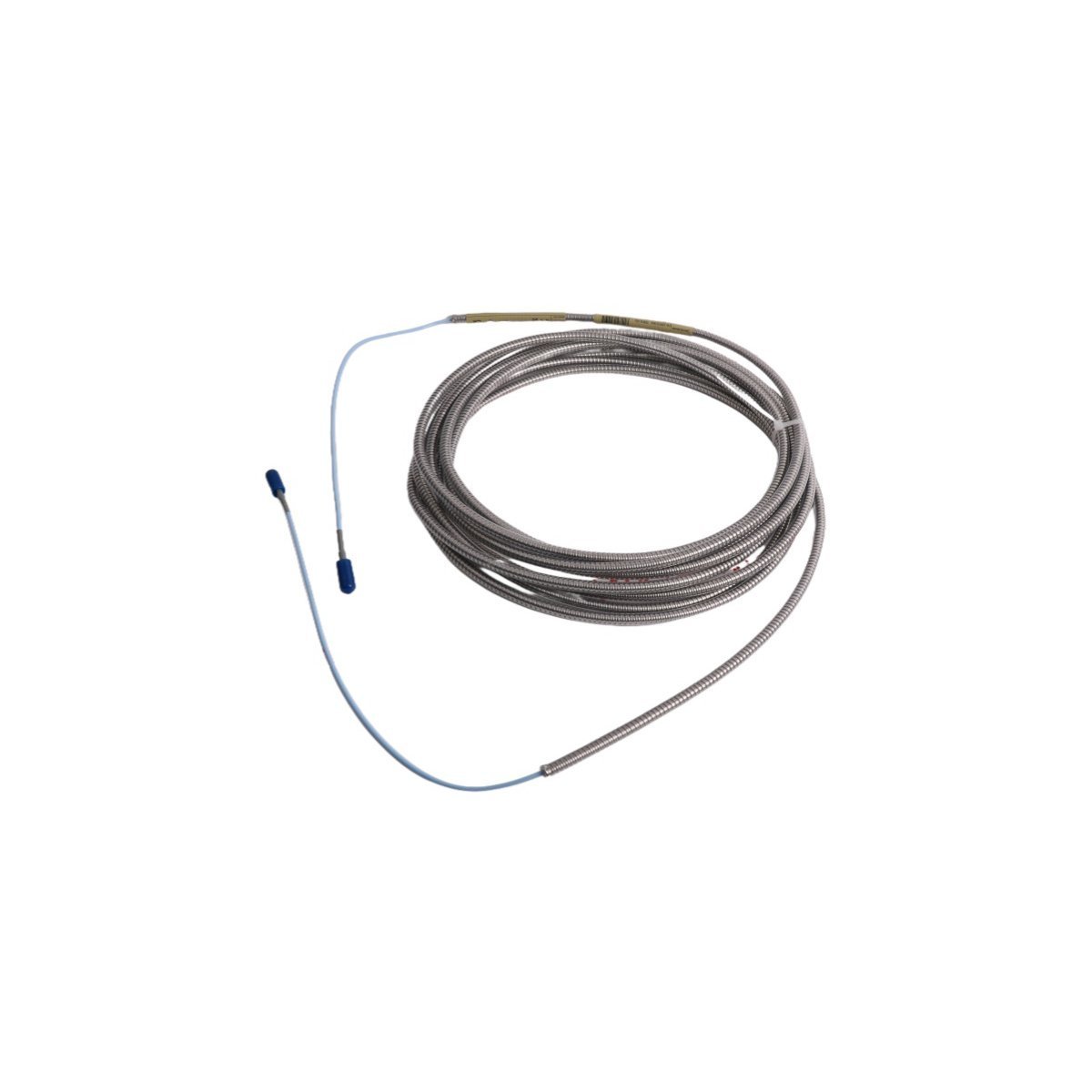
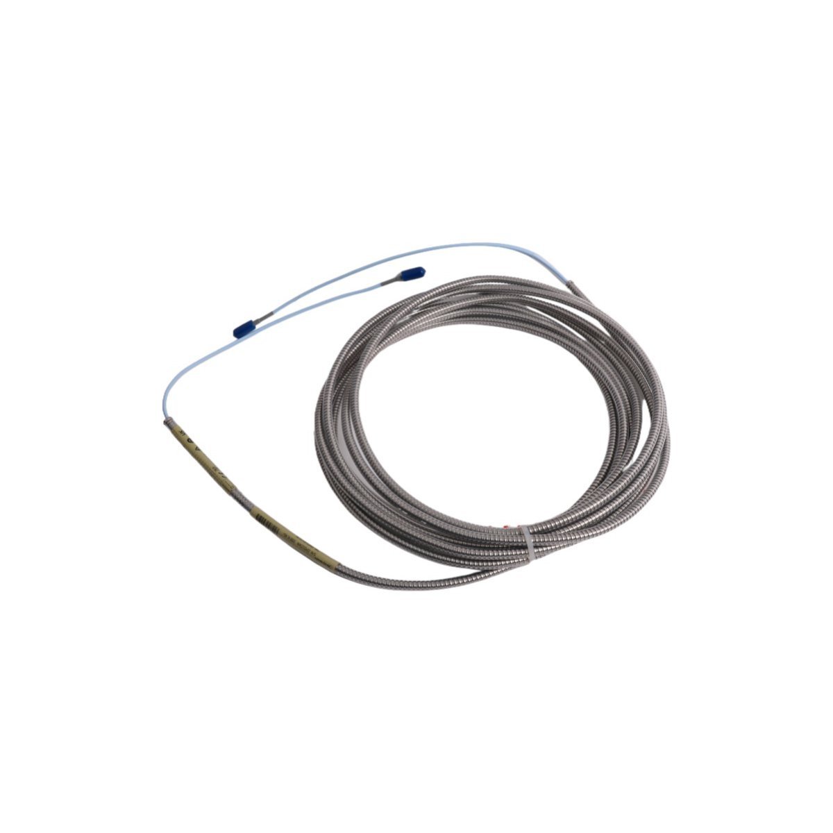
330930-065-01-00 Bently Nevada 3300 XL NSv Extension Cable
Sale!Buy 330930-065-01-00 Bently Nevada 3300 XL NSv Extension Cable in Brand New condition. Original Stock ready for fast Global Shipping to maintain your system.
99 in stock


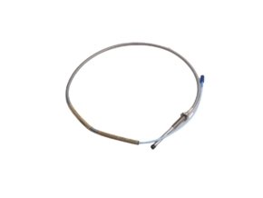
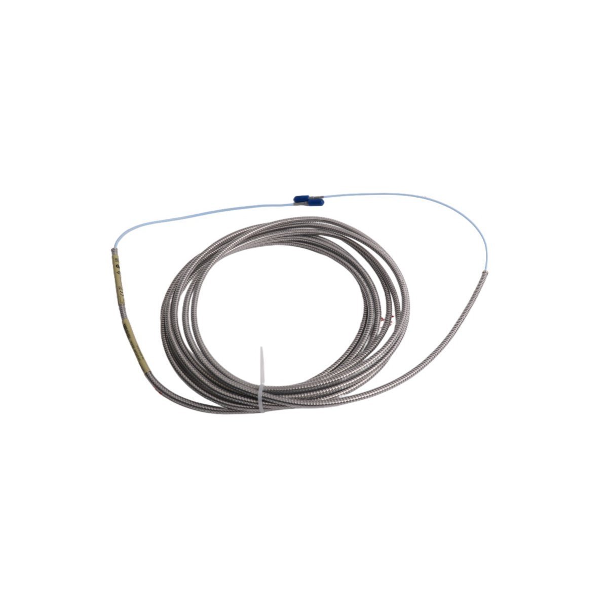
Bently Nevada 330930-065-01-00 3300 XL NSv Extension Cable
The Bently Nevada 330930-065-01-00, also cataloged as the 330930 Extension Cable, operates as a dedicated hardware component for high-frequency signal routing within 3300 XL NSv Proximity Transducer System networks. Engineers deploy this 6.5-meter armored cable to connect non-contact proximity probes to Proximitor Sensors in tight spaces with small shaft targets or counterbores. The integrated ClickLoc coaxial connector pair secures the electrical link, while the stainless steel armor and fluoroethylene propylene (FEP) jacket protect inner signal conductors from mechanical crushing, oil contamination, and ambient radio frequency interference.
Suffix Breakdown & Model Matrix
| Option Code | Parameter Description | Selected Configuration |
|---|---|---|
| 330930 | Base Model Number | 3300 XL NSv Extension Cable |
| -065 | Cable Length Option | 6.5 meters (21.3 feet) |
| -01 | Cable Option | Stainless steel armor with FEP outer jacket |
| -00 | Agency Approval Option | Multiple Approvals |
Hardware Specifications
| Parameter | Specification |
|---|---|
| Model | 330930-065-01-00 |
| Brand | Bently Nevada |
| Origin | USA |
| Weight | 0.55 kg |
| Dimensions | 20.5 x 22.4 x 3.3 cm |
| Operating Temp | -51 deg C to +177 deg C |
| Power Consumption | Passive physical transmission component |
| System Series | 3300 XL NSv Proximity Transducer System |
| Cable Length | 6.5 meters (21.3 feet) |
| Cable Construction | Stainless steel armor with FEP outer jacket |
| Connector Type | Gold-plated ClickLoc miniature coaxial connector |
| Minimum Bend Radius | 25.4 mm (1.0 in) |
Eddy-Current Probe Scaling & Signal Fidelity
Because 3300 XL NSv Proximitor Sensors tune their internal oscillator circuits to match specific system lengths, technicians must pair the 330930-065-01-00 with a probe head whose combined length equals the total target system calibration (typically 7.0 meters). Any mismatch in overall line capacitance skews eddy-current probe scaling, which degrades position and vibration voltage accuracy.
During commissioning, field technicians execute gap voltage validation to ensure that the physical installation yields the nominal -10 VDC baseline offset at the Proximitor output terminals. This target voltage places the probe tip at the midpoint of its linear voltage-to-displacement curve, enabling precise tracking of dynamic shaft orbit behavior and high-speed rotor dynamics. Additionally, proper coaxial shielding throughout the cable length provides cross-talk suppression, preventing adjacent probe carrier signals from coupling into the measurement loop.
Frequently Asked Questions
Q: How do installers verify that the ClickLoc connector remains fully engaged during high-vibration operation?
A: Installers push the male and female coaxial connectors together until the tactile latch engages with a distinct click sound. Technicians then slide the provided silicone boot over the metal junction to seal out moisture and isolate the connector shell from machinery ground loops.
Q: What happens to measurement accuracy if an engineer cuts or splices the 6.5-meter extension cable?
A: Splicing changes the characteristic impedance and electrical capacitance of the cable assembly. This alters the tuned RF resonance of the Proximitor Sensor, shifting the linear scale factor away from its factory specification and rendering gap voltage calibration invalid.
Field Installation Guidelines
Technicians must maintain a minimum bend radius of 25.4 mm along the armored cable run to avoid pinching internal coaxial conductors. Tight bends alter physical conductor spacing, which shifts cable capacitance and alters Proximitor calibration curves.
When routing the cable through machine housings or conduit runs, installers must secure the flexible armor using rubber-lined P-clamps spaced every 300 mm to 450 mm. This clamping strategy isolates the cable from severe mechanical vibration while keeping line tension off terminal connections.
Finally, isolate the external stainless steel armor from structural ground points except at the designated system tie point. Allowing bare armor or exposed metal connector bodies to touch machine frames creates ground loops, introducing low-frequency power line hum and electrical noise into dynamic vibration signals.
| Weight | 0.55 kg |
|---|---|
| Country of Origin | USA |
| Dimension | 20.5 x 22.4 x 3.3cm |


Reviews
There are no reviews yet.