
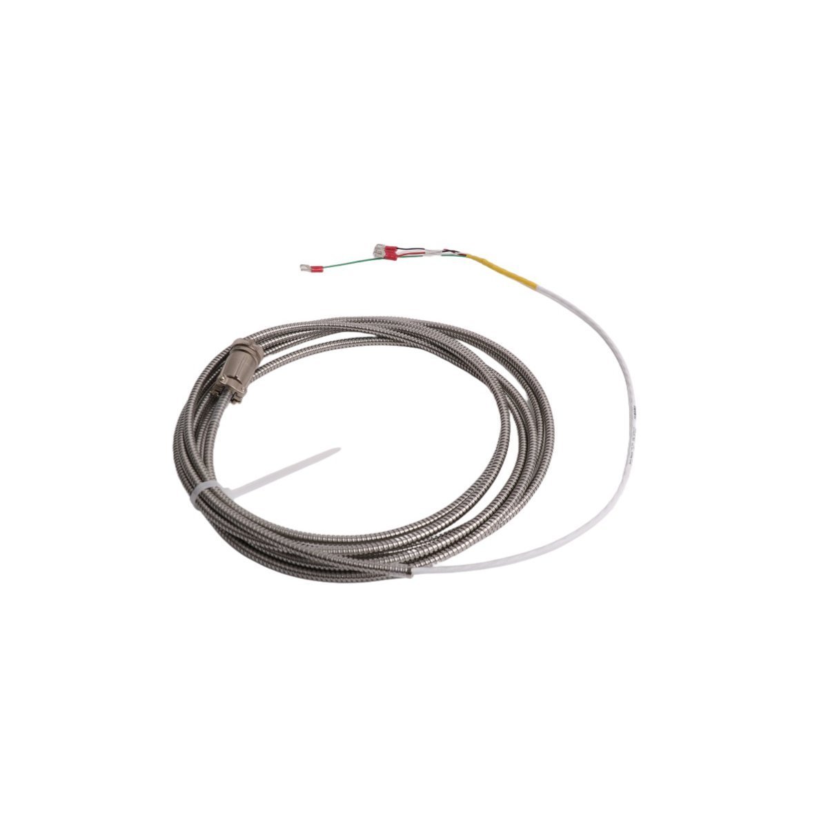
Bently Nevada 16710-17 3300 XL Interconnect Cable
Sale!Bently Nevada 16710-17 Interconnect Cable in Brand New condition. Original Stock available for fast Global Shipping to support your vibration monitoring systems.
99 in stock


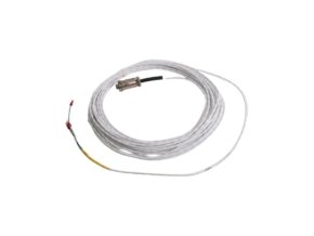
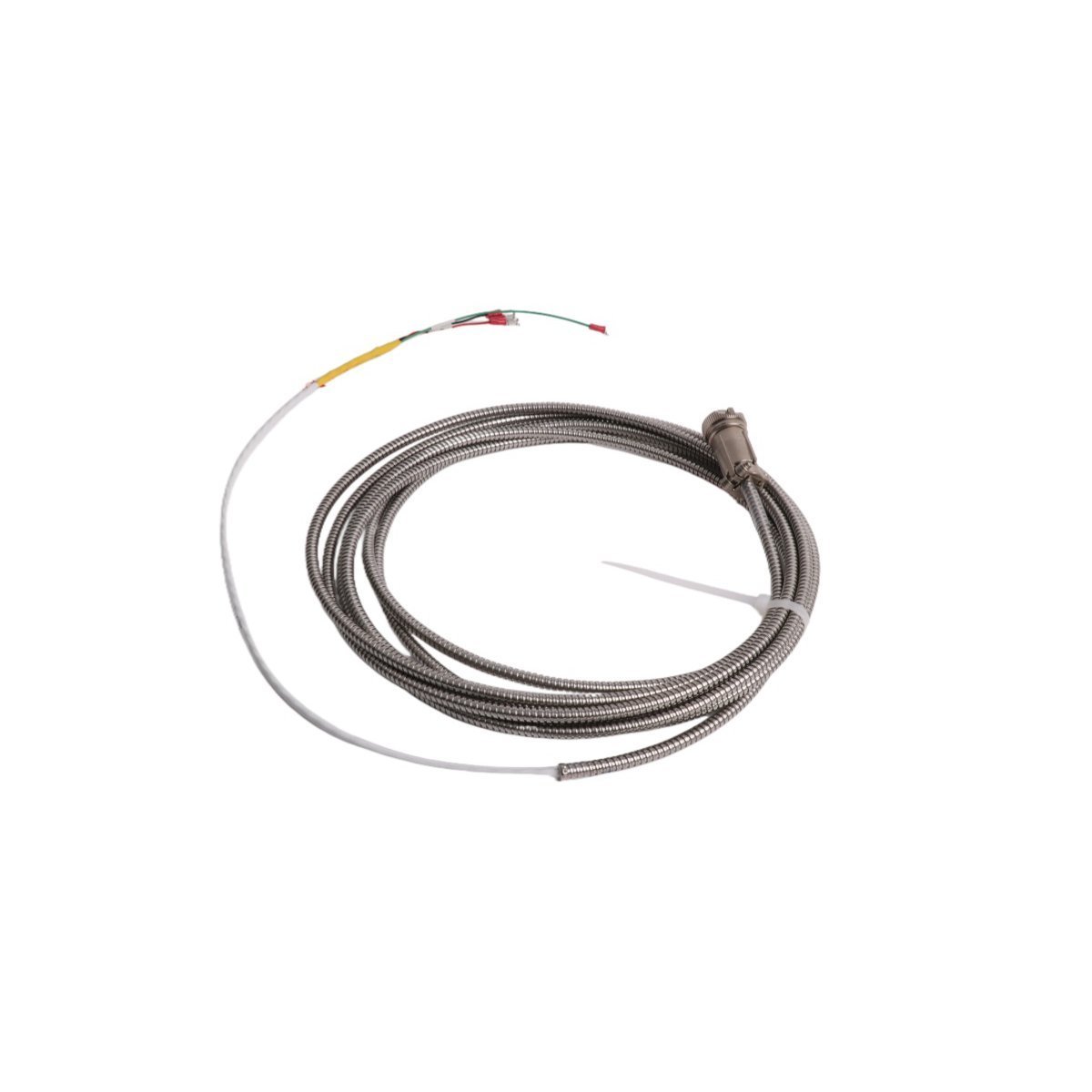
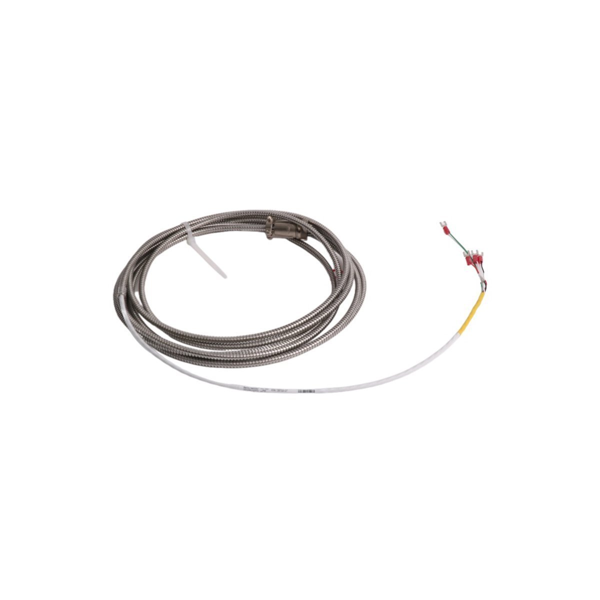
Bently Nevada 16710-17 Interconnect Cable
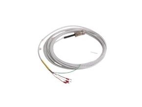
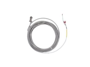
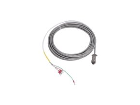
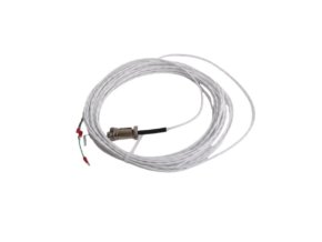
Configured for high-fidelity signal transmission within turbine supervisory instrumentation (TSI) networks, the Bently Nevada 16710-17 (16710 Interconnect Cable) provides direct physical/electrical execution. This specialized assembly links transducer sensors and signal conversion devices to central monitoring racks, transferring raw AC/DC dynamic vibration signals without phase lag or capacitive attenuation. Encased in rugged protective jacketing, the cable maintains shielding continuity against electromagnetic interference, enabling continuous operational tracking across 3300 XL transducer platforms.
Hardware Specifications
| Parameter | Specification |
|---|---|
| Model | 16710-17 |
| Brand | Bently Nevada |
| Origin | USA |
| Weight | 0.08 kg |
| Dimensions | 1.8 x 1.5 x 113 cm |
| Operating Temp | -30 deg C to +80 deg C |
| Power Consumption | Passive physical connection |
| Cable Type | Interconnect cable assembly |
| Cable Length | 17 feet (5.2 meters) / 20 feet options |
| System Compatibility | 3300 XL Proximity Transducer System |
| Signal Compatibility | Raw dynamic voltage and low-current transducer loops |
| Mounting Type | In-line cable interconnect |
Eddy-Current Probe Scaling & Signal Interconnect Integrity
The 16710-17 interconnect cable maintains strict impedance and capacitance limits to preserve eddy-current probe scaling accuracy across long physical runs. Because proximity transducers rely on high-frequency RF carrier signals to measure shaft displacement, any uncontrolled change in cable capacitance shifts the Proximitor Sensor calibration curve. Technicians verify gap voltage validation by measuring the DC bias voltage across the monitoring rack terminal blocks after installing the cable assembly.
Achieving the standard -10 VDC gap voltage target confirms that cable impedance has not degraded signal fidelity between the probe head and monitoring electronics. Furthermore, the cable’s internal multi-strand shielding provides active cross-talk suppression and noise rejection when routed alongside other high-voltage lines. This signal isolation prevents transient electromagnetic pulses from distorting high-speed rotor dynamics tracking, ensuring clean peak-to-peak vibration waveforms for predictive machinery diagnostics.
Frequently Asked Questions
Q: How do technicians maintain proper shield grounding when installing the 16710-17 interconnect cable?
A: Installers ground the outer shield braid exclusively at the monitor rack end while keeping the sensor-side shield insulated. Grounding the cable at a single termination point prevents ground loops, which introduce low-frequency 50 Hz/60 Hz ripple noise into sensitive dynamic vibration channels.
Q: What physical handling precautions prevent signal degradation during cable routing?
A: Technicians must maintain a minimum bend radius of 30 mm along the cable run to avoid pinching internal conductors or altering coaxial insulation spacing. Additionally, installers secure the cable using cushioned clamp ties to prevent mechanical fatigue and microphonic noise caused by machine vibration.
Field Installation Guidelines
Installers must route the 16710-17 interconnect cable inside protective metallic conduits or dedicated low-voltage instrument trays to prevent mechanical damage. Avoid routing this cable parallel to high-voltage AC power lines or variable frequency drive (VFD) output cables; when crossing power wiring is unavoidable, maintain a 90-degree intersection angle to minimize electromagnetic coupling.
Prior to connecting terminal points, inspect all connector pins and sockets for contamination or corrosion. Wipe contacts with isopropyl alcohol if necessary, and ensure threaded connector backshells tighten firmly to prevent loosening from ambient machine vibration.
Leave a 10 cm strain-relief loop near both termination points. This loop absorbs mechanical movement and prevents axial tension on the terminal block screws, preserving conductor integrity during thermal expansion cycles of the machine casing.
| Weight | 0.08 kg |
|---|---|
| Country of Origin | USA |
| Dimension | 1.8 x 1.5 x 113cm |
Reviews
There are no reviews yet.