
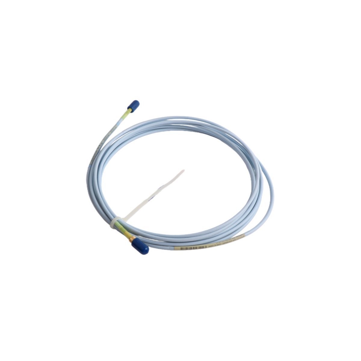
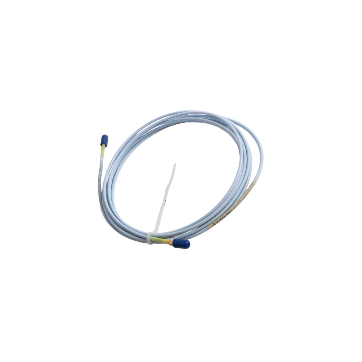
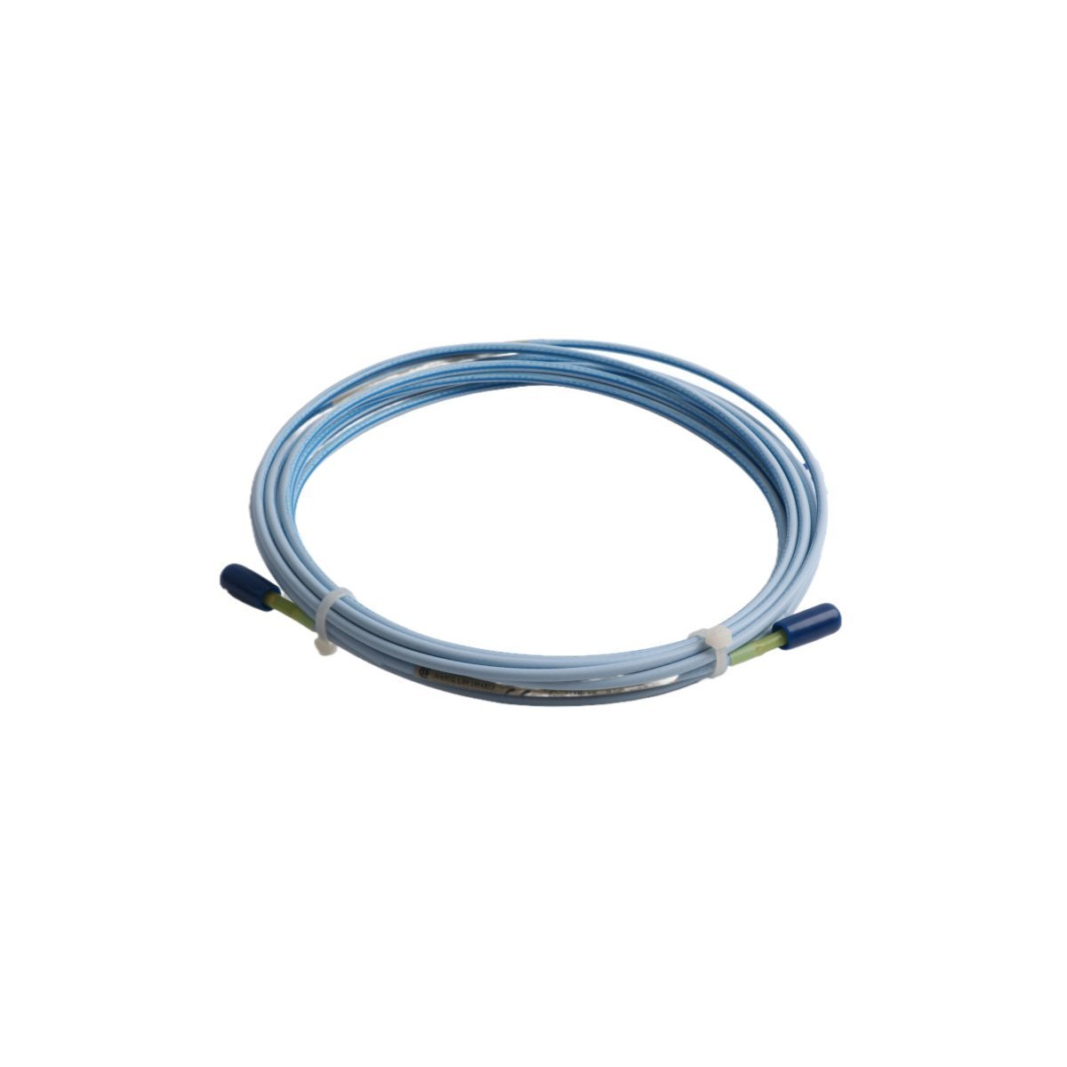
Bently Nevada 330854-40-24-00 3300 XL 25 mm Proximity Extension Cable
Sale!Purchase the Bently Nevada 330854-40-24-00 3300 XL 25 mm extension cable. Factory brand new, original stock. Fast global shipping for TSI industrial machinery protection.
99 in stock


- Maintain Minimum Bend Radii: Field technicians must not exceed the minimum bend radius of 25.4 mm (1.0 inch) for standard coaxial sections during routing. Sharp bends will kink the internal dielectric layer, modify local capacitance values, and cause signal reflections that distort vibration data.
- Observe Torque Limits on Coaxial Connectors: Finger-tighten the miniature coaxial connectors first, and then apply a final torque using the proper connector wrench. Do not use pliers, because excessive force will deform the outer shell and cause intermittent grounding failures.
- Implement Isolation Insulation Sleeves: Always slide clear silicone or Teflon insulation sleeves over the connected coaxial joints before pulling them into cable trays. This prevents the exposed metal connectors from touching structural steel or conduits, which eliminates ground loops.
- Terminal Grounding Protocol: Ensure that the outer shield connects to earth ground only at the Proximitor sensor housing side. Leave the probe-side shield floating to avoid circulating ground currents that introduce noise into the TSI monitoring system.
Bently Nevada 330854-40-24-00 3300 XL 25 mm Extension Cable
The Bently Nevada 330854-40-24-00, also cataloged as the 330854 Extension Cable, operates as a dedicated hardware component for high-frequency electrical signal transmission within 3300 Proximity Transducer System platforms. Engineers deploy this cable to link proximity probes directly to Proximitor sensors, enabling continuous RF signal propagation without impedance mismatch. The hardware maintains electrical continuity and shielding integrity across the entire measurement path, which ensures that raw analog voltage signals move directly from the eddy-current probe to the monitoring backplane without attenuation.
Hardware Specifications
| Parameter | Specification |
|---|---|
| Model | 330854-40-24-00 |
| Brand | Bently Nevada |
| Origin | USA |
| Weight | 0.06 kg |
| Dimensions | 1.8 x 1.6 x 123 cm |
| Operating Temp | -51 to +177 deg C |
| Power Consumption | Passive component (0 mA current draw) |
| System Compatibility | 3300 Proximity Transducer System / TSI |
| Core Calibration Reference | AISI 4140 steel target |
| Connector Type | Miniature coaxial connectors |
| HS Code | 8537101190 |
| Status | Active |
Eddy-Current Probe Scaling and Gap Voltage Validation
Because the cable forms an integral part of the tuned resonant circuit, its physical length and electrical capacitance directly affect the eddy-current probe scaling. Technicians must maintain exact system lengths to preserve the standard calibration slope of 3.94 V/mm (100 mV/mil) or 7.87 V/mm (200 mV/mil) depending on the configuration. During commissioning, engineers perform gap voltage validation to ensure that the static DC voltage sits at the designated -10 VDC targets, which represents the center of the linear operating range. Proper balancing of the extension cable capacitance eliminates signal cross-talk suppression issues when routing multiple transducer lines within a single conduit, thereby preserving accurate tracking of high-speed rotor dynamics.
Frequently Asked Questions
Q: Does the extension cable alter the overall electrical length requirements of the Proximitor system?
A: Yes. The Proximitor sensor requires a specific total electrical length, typically 5.0 or 9.0 meters. Engineers must pair this cable with the correct probe length so that the combined length matches the sensor specification exactly, because any mismatch will alter the calibration slope.
Q: Can maintenance teams interconnect this cable with older, non-XL 3300 series proximity system components?
A: Yes. This hardware maintains physical and technological compatibility with non-XL 3300 5 mm and 8 mm components. This configuration allows direct mechanical interchangeability without requiring changes to existing mounting footprints or spatial allocations.
Q: How does the FluidLoc cable option prevent fluid migration along the internal sheath?
A: The High Temperature FluidLoc cable construction uses internal blocking materials that seal the gaps between individual wire strands. This physical barrier blocks the capillary action of pressurized oils or process fluids, preventing liquid from traveling through the cable into the external junction box.
Field Installation Guidelines
| Weight | 0.06 kg |
|---|---|
| Country of Origin | USA |
| Dimension | 1.8 x 1.6 x 123cm |




Reviews
There are no reviews yet.