
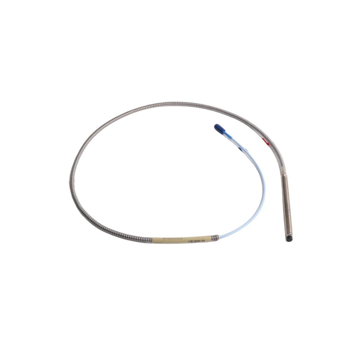
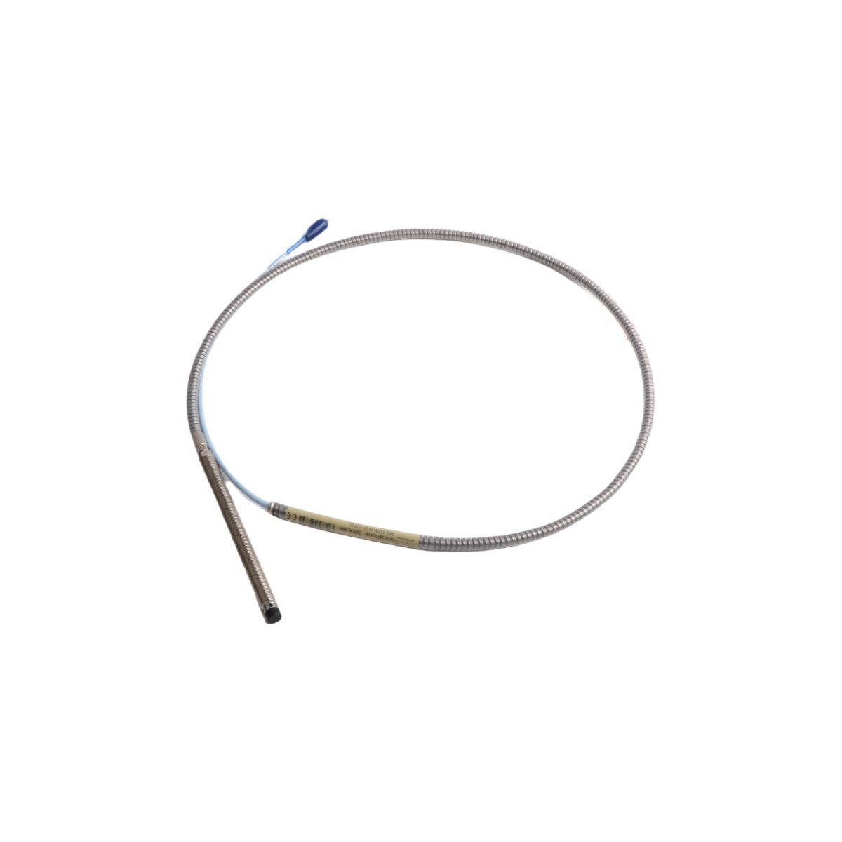
Bently Nevada 330104-00-12-10-02-00 3300 XL Proximity Probe
Sale!Bently Nevada 330104-00-12-10-02-00 3300 XL 8mm proximity probe in Brand New condition. Original Stock ready for fast Global Shipping to maintain your system.
99 in stock


Bently Nevada 330104-00-12-10-02-00 3300 XL 8 mm Proximity Probe
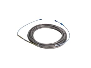
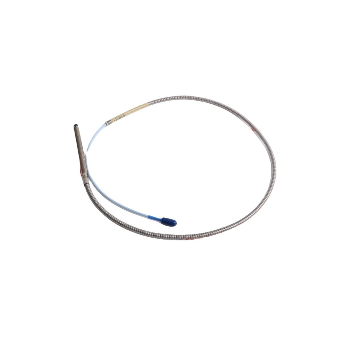
Configured for precise non-contact vibration and axial position monitoring in rotating machinery monitoring systems, the Bently Nevada 330104-00-12-10-02-00 (330104 Proximity Probe) provides direct physical/electrical execution. This eddy-current sensor continuously monitors shaft displacement relative to the probe tip, generating a raw analog voltage signal that reflects real-time mechanical behavior. Encased in a ruggedized M10 x 1 threaded body with integrated flexible armor, this probe maintains structural integrity while transmitting high-frequency mechanical vibration data through its ClickLoc connector interface without signal degradation.
Suffix Breakdown & Model Matrix
| Option Code | Parameter Description | Selected Configuration |
|---|---|---|
| 330104 | Base Model Number | 3300 XL 8 mm Proximity Probe (M10 x 1 Thread) |
| -00 | Unthreaded Length Option | 0.0 in (0 mm) |
| -12 | Overall Case Length Option | 1.2 in (120 mm) |
| -10 | Total Length Option | 1.0 meter (3.3 feet) |
| -02 | Connector & Cable Option | Miniature coaxial ClickLoc connector, armored cable |
| -00 | Agency Approval Option | Multiple Approvals |
Hardware Specifications
| Parameter | Specification |
|---|---|
| Model | 330104-00-12-10-02-00 |
| Brand | Bently Nevada |
| Origin | USA |
| Weight | 0.2 kg |
| Dimensions | 20.5 x 2.4 x 3.3 cm |
| Operating Temp | -51 deg C to +177 deg C |
| Power Consumption | Driven externally via Proximitor Sensor |
| Thread Type | M10 x 1 metric thread |
| Unthreaded Length | 0 mm |
| Case Length | 120 mm |
| Total Cable Length | 1.0 meter |
| Connector Type | ClickLoc miniature coaxial connector |
| Armor Type | Stainless steel flexible armor |
| Sensing Technology | Eddy current non-contact measurement |
Eddy-Current Probe Scaling & Rotor Dynamics
The 330104-00-12-10-02-00 utilizes precise eddy-current probe scaling to convert physical gap changes into proportional electrical signals. When the probe tip approaches a conductive metallic target, the eddy-current field fluctuates, altering the high-frequency RF signal supplied by the matching Proximitor Sensor. Engineers must perform gap voltage validation during installation to establish the precise baseline offset; targeting a nominal -10 VDC gap voltage sets the probe at the midpoint of its linear range (approximately 1.27 mm or 50 mils from the shaft surface).
Because high-speed rotor dynamics demand sub-millimeter precision, proper calibration prevents signal clipping during dynamic shaft orbit transitions. Furthermore, when technicians mount multiple proximity probes in tight proximity within a single bearing housing, they must maintain adequate probe-to-probe clearance. This physical separation provides cross-talk suppression, preventing adjacent high-frequency magnetic fields from distorting critical peak-to-peak vibration waveforms.
Frequently Asked Questions
Q: How does a field engineer accurately verify the -10 VDC gap voltage target during mechanical installation?
A: A technician mounts the probe into the threaded bracket, connects the coaxial lead to the Proximitor Sensor, and applies system power. While monitoring the DC voltage output across the Proximitor signal terminals using a calibrated digital multimeter, the engineer manually rotates the probe body within the M10 x 1 threading. Adjusting the physical distance advances or retracts the tip until the multimeter reads exactly -10 VDC, confirming that the probe rests in the center of its linear voltage-to-displacement curve.
Q: What precautions prevent cross-talk suppression failure when installing paired X-Y radial probes?
A: Installers must maintain a minimum physical distance of 40 mm between probe centers when mounting two 8 mm probes near the same shaft plane. Additionally, engineers should route probe extension cables in separate grounded metallic conduits to shield the high-frequency RF carrier signals from external electromagnetic interference.
Field Installation Guidelines
Installers must strictly observe physical clearance rules and torque limits to prevent mechanical deformation of the probe tip. When inserting the probe through machine casings, maintain a minimum clear counterbore radius of 13 mm around the sensing tip so adjacent structural metal does not alter the eddy-current field calibrated output.
Technicians should tighten the primary mounting nut to a maximum torque of 7.3 N-m (65 in-lb). Exceeding this torque specification risks stripping the internal stainless steel casing threads or buckling the internal coaxial core.
For cable management, preserve a minimum bend radius of 25.4 mm along the armored cable length. Tight bends kink the inner coaxial core, which alters cable capacitance and shifts the Proximitor tuning calibration. Ground the flexible cable armor securely to the machine casing while leaving the ClickLoc connector electrically isolated using the provided silicone terminal sleeves.
| Weight | 0.2 kg |
|---|---|
| Country of Origin | USA |
| Dimension | 20.5 x 2.4 x 3.3cm |


Reviews
There are no reviews yet.