
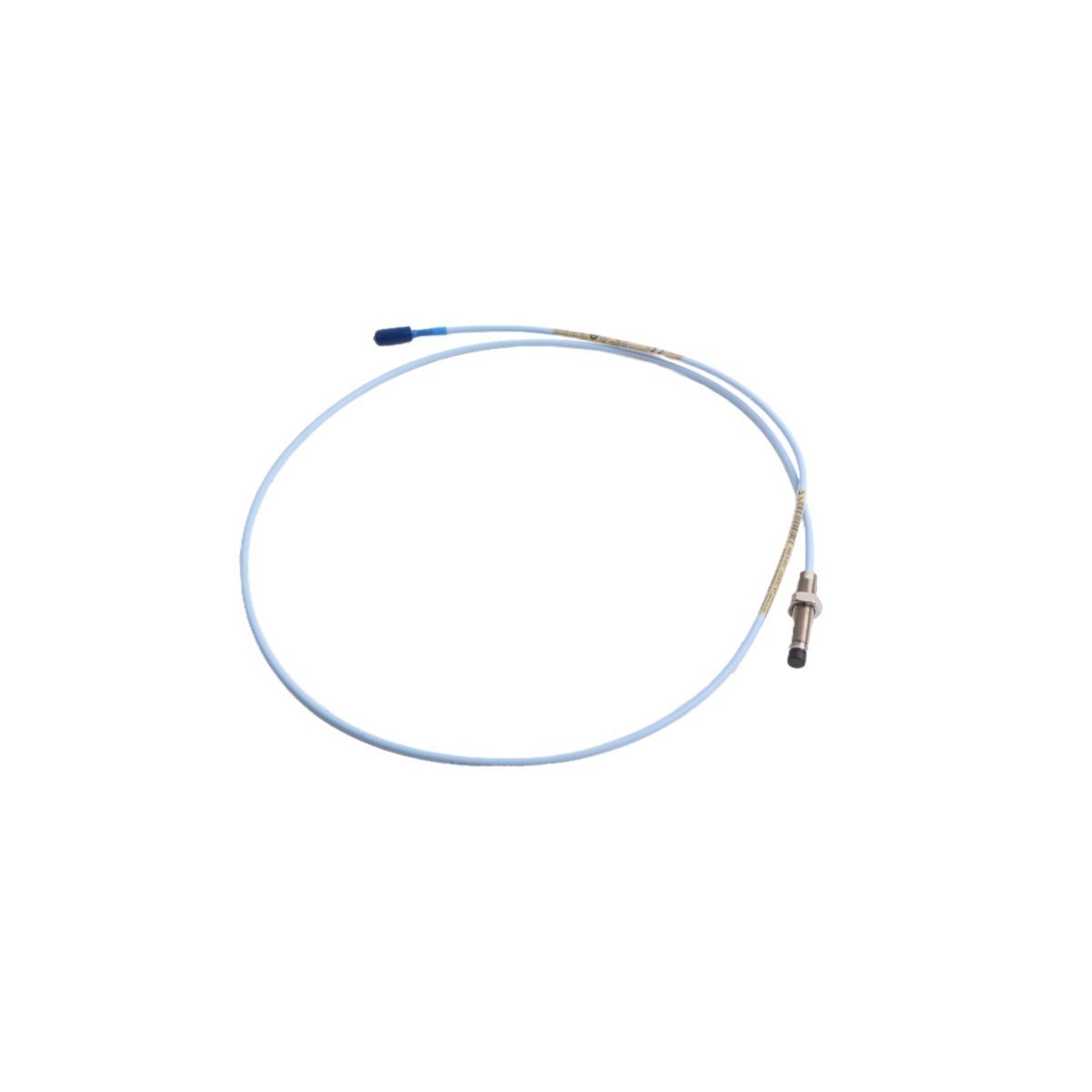
330101-00-17-20-12-05 Bently Nevada 3300 XL 8 mm Proximity Probe
Sale!Order 330101-00-17-20-12-05 Bently Nevada 3300 XL Proximity Probe. Brand New condition, Original Stock ready for Global Shipping to protect industrial rotating machinery.
99 in stock


Bently Nevada 330101-00-17-20-12-05 3300 XL 8 mm Proximity Probe
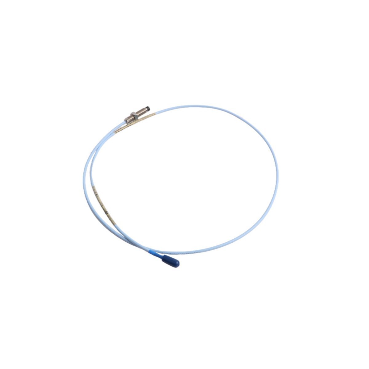
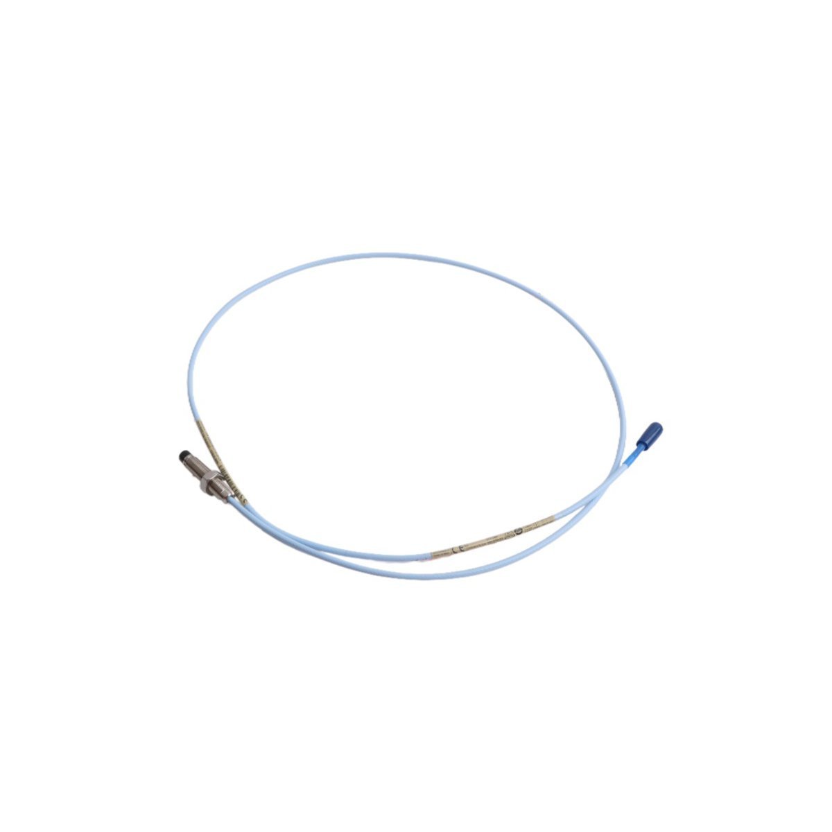
The Bently Nevada 330101-00-17-20-12-05 serves as the primary 330101 Proximity Probe utilized to execute non-contact shaft vibration and axial position measurement across turbine supervisory instrumentation (TSI) platforms. The physical sensing tip generates high-frequency eddy currents in response to target proximity, converting mechanical displacement into a linear raw voltage signal. Featuring a 3/8-24 UNF threaded casing, integrated CableLoc armor with 330 N tensile strength, and gold-plated ClickLoc connectors, this assembly transfers signal variations directly to the matching 3300 XL Proximitor Sensor without phase lag or amplitude distortion.
Suffix Breakdown & Model Matrix
| Option Code | Parameter Description | Selected Configuration |
|---|---|---|
| 330101 | Base Model Number | 3300 XL 8 mm Proximity Probe (3/8-24 UNF Thread) |
| -00 | Unthreaded Length Option | 0.0 in (0 mm) |
| -17 | Overall Case Length Option | 1.7 in (43 mm) |
| -20 | Total Length Option | 2.0 meters (6.6 feet) |
| -12 | Connector & Cable Option | Armored cable, FluidLoc cable, ClickLoc connector |
| -05 | Agency Approval Option | Multiple Approvals (CSA, ATEX, IECEx) |
Hardware Specifications
| Parameter | Specification |
|---|---|
| Model | 330101-00-17-20-12-05 |
| Brand | Bently Nevada |
| Origin | USA |
| Weight | 0.06 kg |
| Dimensions | 1.8 x 1.6 x 123 cm |
| Operating Temp | -51 deg C to +177 deg C |
| Power Consumption | Driven externally via 3300 XL Proximitor Sensor |
| Thread Type | 3/8-24 UNF thread |
| Unthreaded Length | 0.0 in (0 mm) |
| Case Length | 1.7 in (43 mm) |
| Total Cable Length | 2.0 m (6.6 ft) |
| Cable Pull Strength | CableLoc design with 330 N (75 lbf) pull strength |
| Connector Type | Gold-plated ClickLoc coaxial connector |
| Liquid Sealing | FluidLoc barrier prevents fluid penetration |
| Hazardous Approvals | CSA, ATEX, IECEx certified |
Gap Voltage Validation & Rotor Dynamics
Field engineers calibrate the 330101-00-17-20-12-05 probe to analyze complex rotor dynamics across high-speed machinery trains. Because physical shaft movement modulates the RF field generated by the probe tip, technicians must execute gap voltage validation before locking down the mounting assembly. The baseline setting requires a -10.0 VDC target, which establishes the sensor at the midpoint of its linear operating sweep (approximately 1.0 mm distance from the target metallic surface).
While adjusting the probe within its 3/8-24 UNF threaded mount, the technician reads DC voltage across the Proximitor Sensor output terminals using a multimeter. Achieving an exact -10.0 VDC bias ensures that dynamic peak-to-peak shaft vibrations do not drive the signal into non-linear saturation regions. Consequently, this precise mechanical offset prevents signal clipping during unexpected rotor thermal expansion or transient vibration spikes.
Frequently Asked Questions
Q: How does the TipLoc and CableLoc construction protect signal integrity under mechanical stress?
A: The TipLoc molding process creates a continuous chemical bond between the probe tip substrate and the outer housing, which prevents tip detachment under high fluid shear force. Simultaneously, the CableLoc design anchors the internal coaxial cabling directly to the casing, providing 330 N (75 lbf) of pull resistance against mechanical strain during routine overhauls.
Q: Why do technicians specify FluidLoc cable options for oil-lubricated bearing housings?
A: Standard coaxial cables permit lubricating oils to migrate through internal wire strands via capillary action, which eventually forces oil past seals into external junction boxes. The FluidLoc internal barrier blocks liquid passage along the cable core, maintaining total oil containment inside the machine housing while preserving high-frequency signal propagation.
Field Installation Guidelines
Technicians must observe precise spatial clearance rules during installation to prevent signal distortion. First, maintain an unthreaded counterbore clearance of at least 13 mm radius around the probe tip. Adjacent structural metal inside this radius interferes with the eddy-current field and alters calibrated voltage output.
Second, thread the probe into the mounting bracket using hand force until the tip approaches the target shaft surface. While monitoring DC voltage at the Proximitor Sensor terminals, adjust the probe depth until the multimeter displays -10.0 VDC. Tighten the locknut to a maximum torque of 8 N-m (70 in-lb); exceeding this limit deforms the 3/8-24 UNF external threads and stresses internal coaxial shielding.
Finally, route the 2.0 m armored cable through grounded metal conduit, maintaining a minimum bend radius above 25.4 mm to prevent coaxial impedance shifts. Clean all gold-plated ClickLoc connectors with contact cleaner prior to mating, and slide the supplied silicone terminal sleeves over the connector body to prevent electrical ground loops.
| Weight | 0.06 kg |
|---|---|
| Country of Origin | USA |
| Dimension | 1.8 x 1.6 x 123cm |



Reviews
There are no reviews yet.