
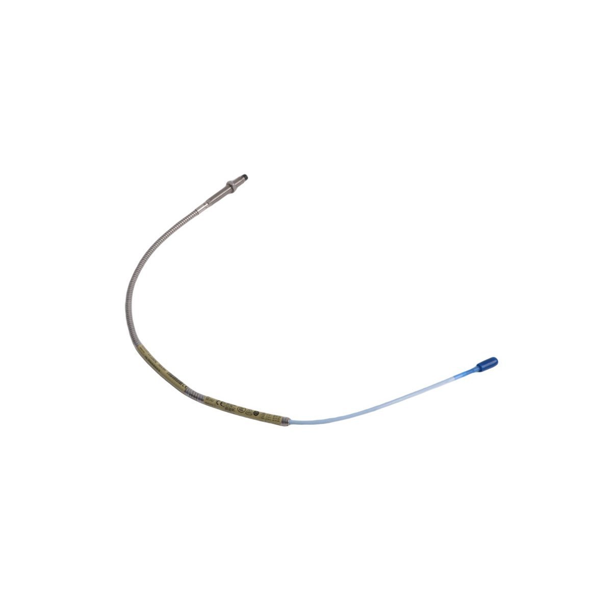
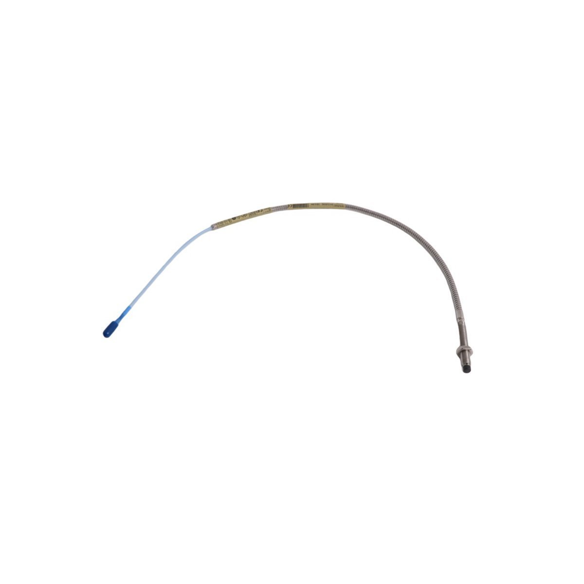
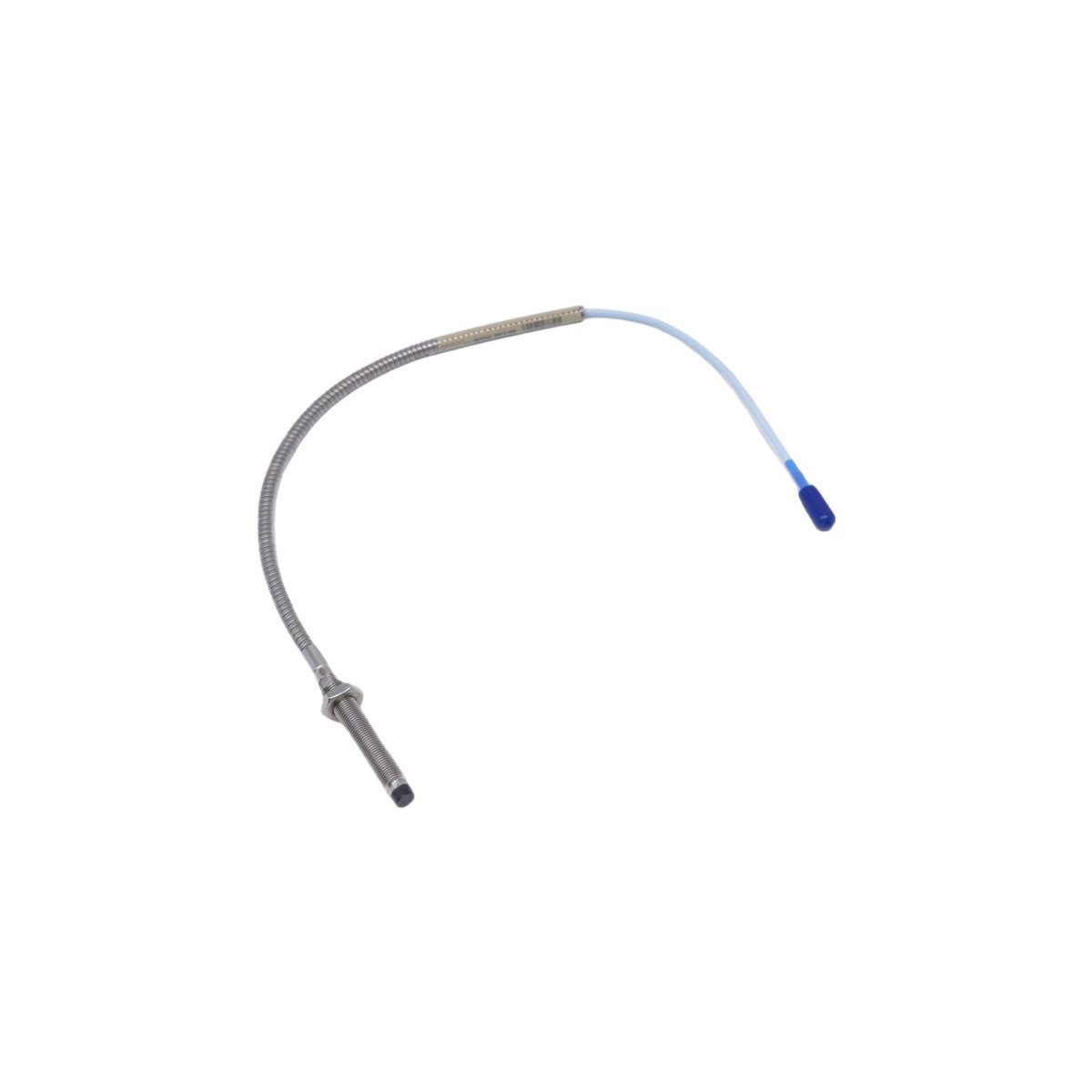
Bently Nevada 330104-00-06-05-01-05 3300 XL 8 mm Proximity Sensors Probe
Sale!Purchase the Bently Nevada 330104-00-06-05-01-05 3300 XL 8 mm Probe. Brand New item in Original Stock with Global Shipping. Features M10 thread and ATEX approvals.
99 in stock


Bently Nevada 330104-00-06-05-01-05 3300 XL 8 mm Proximity Probes
The Bently Nevada 330104-00-06-05-01-05, also cataloged as the 330104 Proximity Sensors, operates as a dedicated hardware component for vibration and position measurements within TSI platforms. Engineers thread this non-contact eddy-current transducer into machinery housing to capture dynamic shaft displacement and static position data. The physical probe body transmits high-frequency magnetic field shifts through a miniature coaxial ClickLoc connector, which delivers raw voltage signals directly to the matching Proximitor Sensor loop.
Suffix Breakdown & Model Matrix
| Option Segment | Value | Specification Description |
|---|---|---|
| Unthreaded Length | 00 | 0.0 in unthreaded length |
| Overall Case Length | 06 | 60 mm total case length |
| Total Length | 05 | 0.5 meter (20 in) system cable length |
| Connector Option | 01 | Miniature coaxial ClickLoc connector |
| Agency Approval | 05 | Multiple approvals (CSA, ATEX, IECEx) |
Hardware Specifications
| Parameter | Specification |
|---|---|
| Model | 330104-00-06-05-01-05 |
| Brand | Bently Nevada |
| Origin | USA |
| Weight | 0.12 kg |
| Dimensions | 20.4 x 22.4 x 3.5 cm |
| Operating Temp | Standard system rating up to 177 deg C |
| Power Consumption | Passive sensor (loop-powered by 3300 XL Proximitor Sensor) |
| Mounting Thread | M10 x 1 metric thread |
| Cable Length | 0.5 meter |
| Target Material | AISI 4140 steel standard (eddy-current target) |
| System Compatibility | 3300 XL Proximity Transducer System |
| HS Code | 8537101190 |
Gap Voltage Validation and Eddy-Current Probe Scaling
The system drives high-frequency AC current into the probe tip, generating an alternating magnetic field that penetrates the conductive shaft surface. Relative motion between the target surface and the 8 mm tip shifts the field amplitude, allowing the Proximitor Sensor to scale the electrical impedance into an analog voltage output. Maintenance personnel conduct gap voltage validation by adjusting mechanical positioning until the signal reads a nominal -10 VDC target at the mid-point of the linear range. Furthermore, the internal coil design maintains linear sensitivity while rejecting cross-talk suppression between adjacent probes during high-speed rotor dynamics monitoring.
Frequently Asked Questions
Q: How does the ClickLoc connector maintain electrical continuity under mechanical vibration? A: The gold-plated ClickLoc connector features an internal mechanical latching ring. When technicians snap the mating halves together, the mechanism locks with an audible click, preventing contact oxidation and vibrational separation.
Q: Does this probe assembly require external isolation plates to prevent ground loops? A: No, the sensor architecture provides intrinsic electrical isolation from the machine housing. Consequently, technicians mount the M10 body directly into grounded machinery casing without installing dielectric isolator plates.
Q: What installation steps allow this probe to meet RFI immunity standards in harsh electrical environments? A: Technicians pair the probe directly with a standard 3300 XL Proximitor Sensor. Because the combined system design inherently resists electromagnetic interference, the assembly achieves full CE compliance without requiring external metal shielding enclosures.
Field Installation Guidelines
Technicians must observe precise mechanical sequence during mounting. First, inspect the tapped M10 x 1 port for burrs and clean all debris from the target surface. Thread the probe into the port by hand while carefully rotating the integrated cable to avoid twisting the internal coaxial conductor. Next, connect a digital multimeter across the Proximitor Sensor output terminals to monitor DC gap voltage. Advance or back off the probe body until the output matches the required physical gap voltage (typically -10 VDC), then torque the locknut against the machine casing to secure the setting.
Route the 0.5-meter coaxial cable through protective conduit, keeping the bend radius above the minimum 25.4 mm threshold to prevent structural deformation. Slide the supplied connector protector over the miniature coaxial ClickLoc connection, snapping the halves tightly together. Finally, terminate the extension cable braid at the dedicated terminal bus while ensuring grounding occurs at a single point to prevent ground loop noise from corrupting the TSI channel.
| Weight | 0.12 kg |
|---|---|
| Country of Origin | USA |
| Dimension | 20.4 x 22.4 x 3.5cm |


Reviews
There are no reviews yet.