Purchase the 330101-33-66-10-02-05 Bently Nevada 8 mm probe. Verified Brand New, Original Stock units ready for Global Shipping to support your TSI machinery systems.
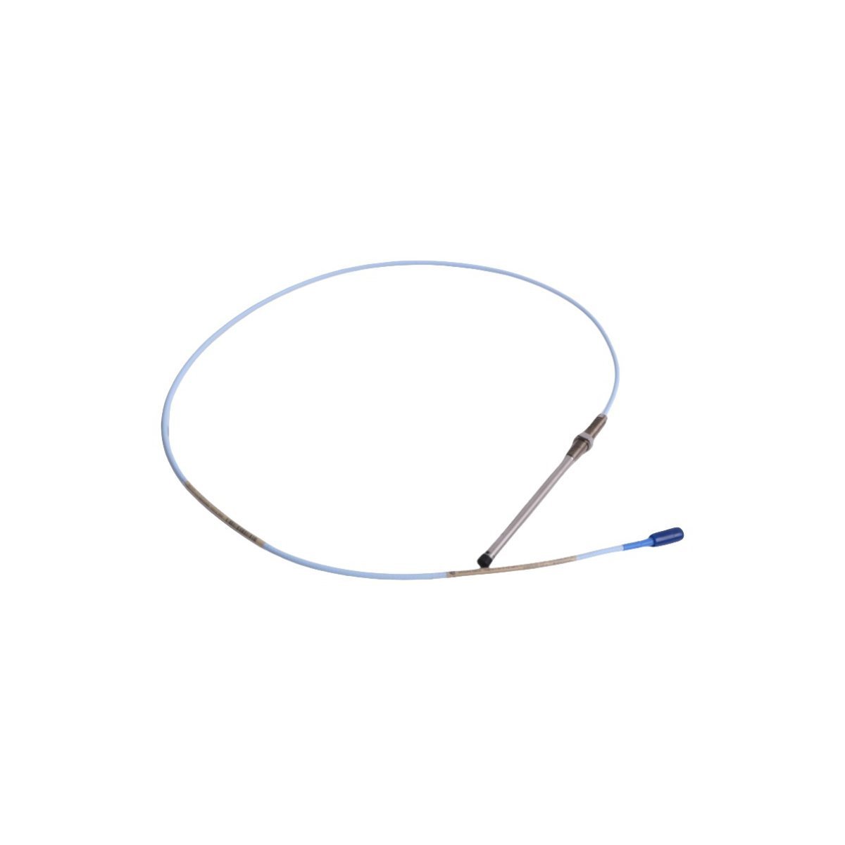
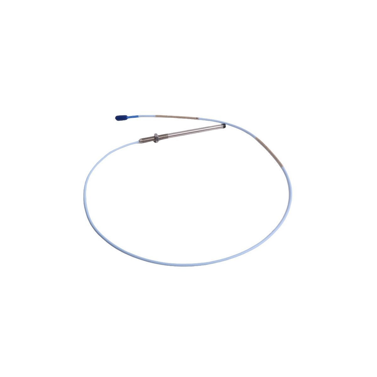
Bently Nevada 330101-33-66-10-02-05 3300 XL 8 mm Proximity Probes
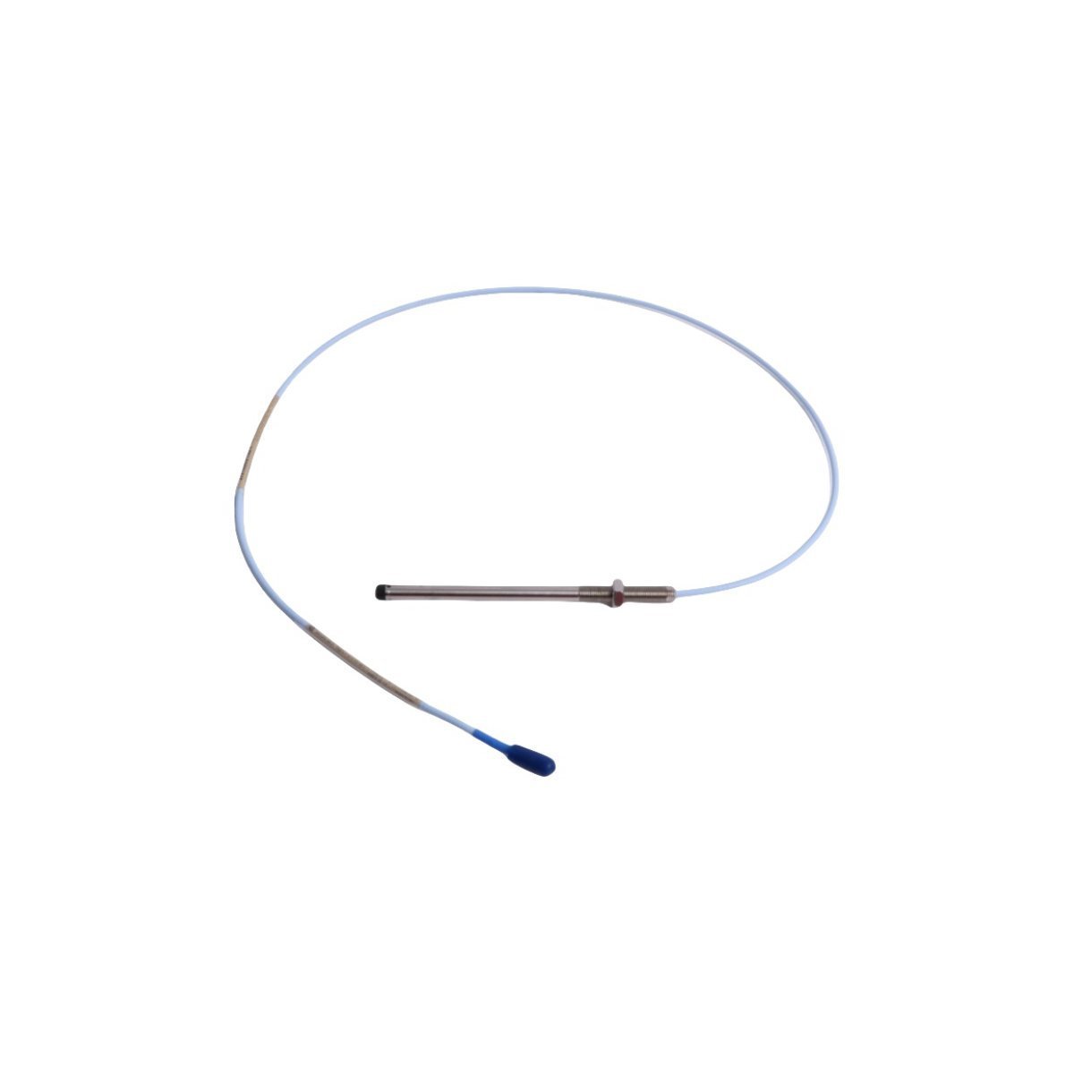
The Bently Nevada 330101-33-66-10-02-05, also cataloged as the 330101-33-66-10-02-05 Proximity Probes, operates as a dedicated hardware component for contactless position and vibration measurements within TSI platforms. Engineers specify this 8 mm transducer probe to observe target surface displacements directly, converting mechanical gaps into proportional electrical signals for continuous machinery protection.
Hardware Specifications
Parameter
Specification
Model
330101-33-66-10-02-05
Brand
Bently Nevada
Origin
USA
Weight
0.04 kg
Dimensions
110 x 1.5 x 1.2 cm
Operating Temp
Standard industrial probe operating range
Power Consumption
Passive sensor (powered via Proximitor Sensor loop)
Mounting Thread
3/8-24 UNF thread
Cable Type
1.0 m standard unarmored coaxial cable
Connector Type
Miniature coaxial ClickLoc connector
Agency Approvals
CSA, ATEX, IECEx
Eddy-Current Probe Scaling and Gap Voltage Validation
Because the sensor relies on high-frequency magnetic fields, technicians must strictly verify eddy-current probe scaling during commissioning. Consequently, operators establish baseline gap voltage validation targeting -10 VDC at the mid-point of the physical linear range. Proper mechanical alignment prevents signal saturation, which in turn optimizes cross-talk suppression when running parallel probe leads across dynamic shaft locations. This approach allows the downstream monitor to calculate rotor dynamics without field distortion.
Frequently Asked Questions
Q: How does the ClickLoc coaxial connector ensure signal integrity under operational vibration?
A: The ClickLoc design locks the miniature coaxial connection in place, so the assembly maintains physical contact and constant resistance even when subjected to machine vibration.
Q: Why must technicians verify the -10 VDC gap voltage baseline prior to securing the probe locknut?
A: Setting the output voltage to -10 VDC positions the probe tip in the center of its linear electrical range; therefore, the system accurately captures full peak-to-peak shaft displacement without driving the signal out of range.
Field Installation Guidelines
Installers thread the probe into a pre-tapped 3/8-24 UNF mounting hole, advancing the assembly manually until the probe tip approaches the target surface. Next, technicians connect a multimeter across the sensor loop, fine-tuning the mechanical insertion depth until the meter displays the target gap voltage. As soon as the voltage stabilizes, field crews apply specified torque to the locknut, locking the probe position permanently. Finally, maintenance teams route the unarmored cable through protective conduit runs, grounding the shield at the junction box to eliminate external interference.
Weight
0.04 kg
Country of Origin
USA
Dimension
110 x 1.5 x 1.2cm
Reviews
There are no reviews yet.
Be the first to review “Bently Nevada 330101-33-66-10-02-05 3300 XL Proximity Sensors” Cancel reply





Reviews
There are no reviews yet.