
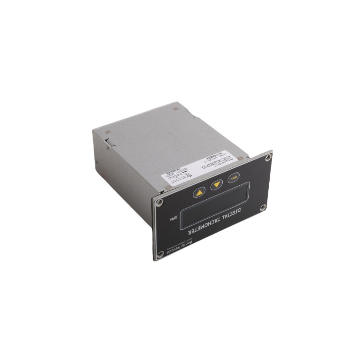
Bently Nevada 174652-01 TACH100-01 Digital Tachometer Module
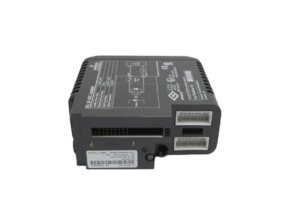
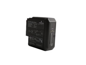
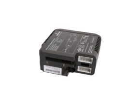
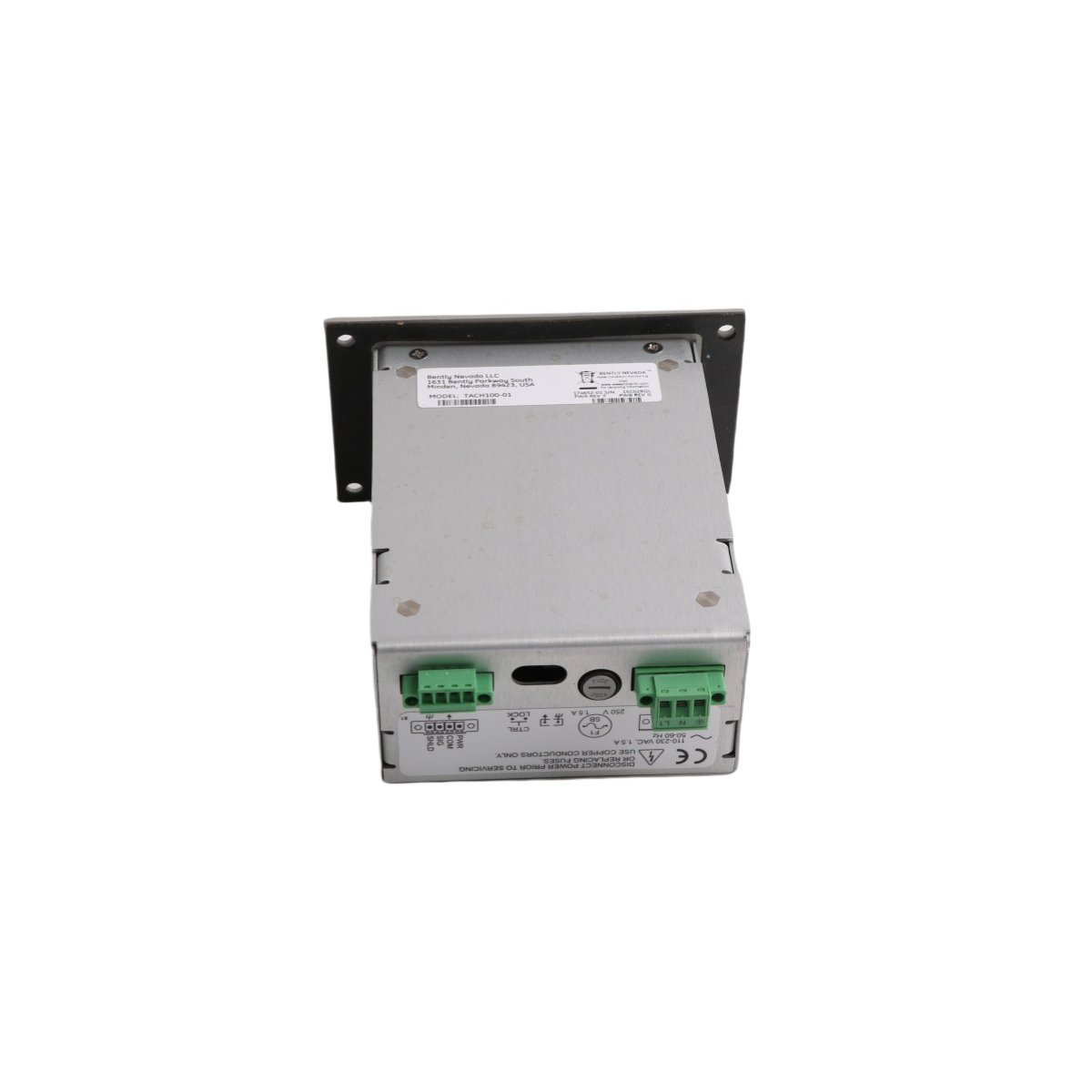
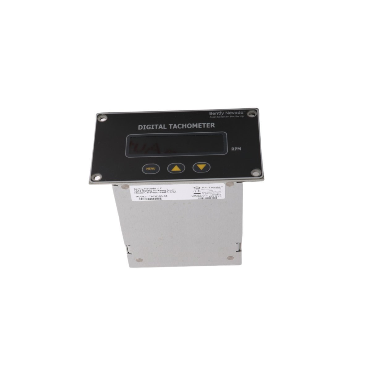
Sale!The TACH100-01 174652-01 is a Bently Nevada 3300 series compatible digital tachometer. This hardware is Brand New from Original Stock with Global Shipping.
99 in stock


- Mount the tachometer unit inside a protected enclosure to safeguard the display assembly from direct moisture or corrosive chemical contact.
- Strip the sensor input insulation back by exactly 6 mm before inserting the conductors into the terminal blocks, tightening the screws to prevent vibration-induced contact resistance.
- Ground the incoming coaxial cable shield at the instrument rack end only, eliminating parasitic ground loop currents from injecting noise into the speed calculation register.
- Verify the input voltage configuration matches the factory supply limits prior to energizing the main terminal block.
- Mount the tachometer unit inside a protected enclosure to safeguard the display assembly from direct moisture or corrosive chemical contact.
- Strip the sensor input insulation back by exactly 6 mm before inserting the conductors into the terminal blocks, tightening the screws to prevent vibration-induced contact resistance.
- Ground the incoming coaxial cable shield at the instrument rack end only, eliminating parasitic ground loop currents from injecting noise into the speed calculation register.
- Verify the input voltage configuration matches the factory supply limits prior to energizing the main terminal block.
Bently Nevada TACH100-01 174652-01 Digital Tachometer
The Bently Nevada TACH100-01, also cataloged as the 174652-01 Digital Tachometer, serves as the primary TACH100 Digital Tachometer utilized to execute speed measurement and Keyphasor signal processing across TSI platforms. The hardware functions as an independent local speed indicator or interfaces directly with permanent machinery protection architectures. By generating an internal sensor power rail and conditioning raw pulse frequency inputs, the device provides real-time rotational velocity computation without disrupting parallel measurement loops.
Hardware Specifications
| Parameter | Specification |
|---|---|
| Model | TACH100-01 174652-01 |
| Brand | Bently Nevada |
| Origin | USA |
| Weight | 0.48 kg |
| Dimensions | 14 x 16 x 7.5 cm |
| Operating Temp | -20 deg C to +65 deg C |
| Power Consumption | 1.01 W |
| Input Supply Voltage | 110 to 230 VAC, 50 to 60 Hz |
| Internal Fuse Protection | 1.5 A Slow-Blow (SB) |
| Sensor Power Output | -24 VDC to Proximitor sensors |
| Measurement Range | 0 to 30000 RPM |
| Pulses Per Revolution | 1 to 99 events per revolution |
| Hysteresis Range | 0.2 to 2.5 VDC (Field-configurable) |
| HS CODE | 8537101190 |
| MOQ | 1 |
Machinery Monitoring & TSI Characteristics
The module executes speed processing by matching the input signal characteristics to established eddy-current probe scaling baselines. An automatic threshold adjustment circuit tracks incoming raw pulses, while the system enforces a specific gap voltage validation window to maintain stable triggering. This design enables the hardware to isolate valid Keyphasor events from ambient background noise. Engineers alter the field-configurable hysteresis between 0.2 VDC and 2.5 VDC to stabilize measurements during complex rotor dynamics events. Furthermore, high-impedance input isolation provides cross-talk suppression, which prevents the tachometer from corrupting primary signals when connected in parallel with permanent monitoring racks.
Frequently Asked Questions
Q: Does the parallel connection to an existing Proximitor loop introduce signal loss or measurement distortion?
A: No, the tachometer incorporates high-impedance buffer stages that prevent loading effects, allowing the hardware to sample the Keyphasor pulse without dropping loop voltage.
Q: How does the device respond to unexpected electrical faults or incoming line surges?
A: An internal 1.5 A slow-blow fuse interrupts the primary power circuit during overcurrent conditions, which isolates the internal power transformer and shields the connected transducer lines.
Q: What mechanisms handle speed fluctuations that exceed the standard 30000 RPM limit?
A: The microcontroller stops updating the display register when input pulse frequencies surpass the processing clock limits, indicating an over-range condition until the frequency returns to the rated linear range.
Field Installation Guidelines
Machinery Monitoring & TSI Characteristics
The module executes speed processing by matching the input signal characteristics to established eddy-current probe scaling baselines. An automatic threshold adjustment circuit tracks incoming raw pulses, while the system enforces a specific gap voltage validation window to maintain stable triggering. This design enables the hardware to isolate valid Keyphasor events from ambient background noise. Engineers alter the field-configurable hysteresis between 0.2 VDC and 2.5 VDC to stabilize measurements during complex rotor dynamics events. Furthermore, high-impedance input isolation provides cross-talk suppression, which prevents the tachometer from corrupting primary signals when connected in parallel with permanent monitoring racks.
Frequently Asked Questions
Q: Does the parallel connection to an existing Proximitor loop introduce signal loss or measurement distortion?
A: No, the tachometer incorporates high-impedance buffer stages that prevent loading effects, allowing the hardware to sample the Keyphasor pulse without dropping loop voltage.
Q: How does the device respond to unexpected electrical faults or incoming line surges?
A: An internal 1.5 A slow-blow fuse interrupts the primary power circuit during overcurrent conditions, which isolates the internal power transformer and shields the connected transducer lines.
Q: What mechanisms handle speed fluctuations that exceed the standard 30000 RPM limit?
A: The microcontroller stops updating the display register when input pulse frequencies surpass the processing clock limits, indicating an over-range condition until the frequency returns to the rated linear range.
Field Installation Guidelines
| Weight | 0.48 kg |
|---|---|
| Country of Origin | USA |
| Dimension | 14 x 16 x 7.5cm |
Reviews
There are no reviews yet.