
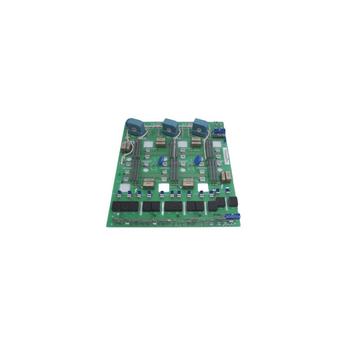
ABB SDCS-PIN-11 3ADT306100R1 DCS600 Power Interface Boards
Sale!Purchase the ABB SDCS-PIN-11 3ADT306100R1 Power Interface Board for DCS600 systems. Brand New unit in Original Stock with fast Global Shipping. View full specifications.
99 in stock


- Frame Isolation and Static Dissipation: Installers must verify that the cabinet ground rail establishes low-impedance bonding with the main plant ground system. Operators must wear a calibrated electrostatic discharge (ESD) wrist strap during unboxing and physical rail attachment routines to protect internal logic gates from static overvoltage breakdown.
- Mounting Clearances and Ventilation paths: Secure the 28.1 x 25.4 x 4.0 cm enclosure inside the chassis partition while maintaining standard 50 mm surrounding clearance margins. Adequate physical space allows convective cross-flows to dissipate internal heat loads without relying on external forced air.
- Signal Conduit Separation: Route high-voltage gate firing conductors and low-voltage digital signal pairs in separate, isolated wire trays. Physical spacing mitigates electromagnetic cross-talk risks and isolates the sensitive internal communication electronics from sudden current surges.
- Terminal Block Torquing Specifications: Secure all input power lines and interface connection blocks to the factory-marked tightness settings using calibrated manual drivers. Loose connection loops cause localized thermal resistance increases, which damages electrical continuity over long operation cycles.
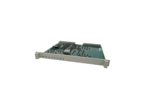
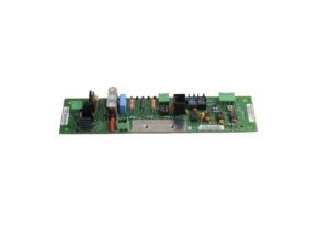
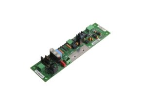
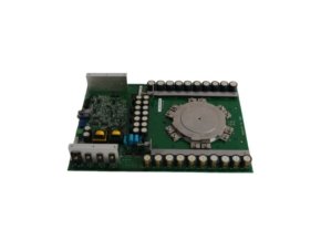
ABB SDCS-PIN-11 3ADT306100R1 Power Interface Board
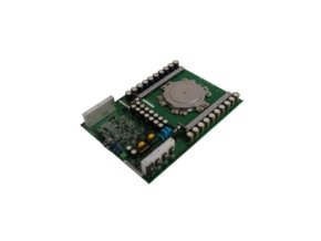
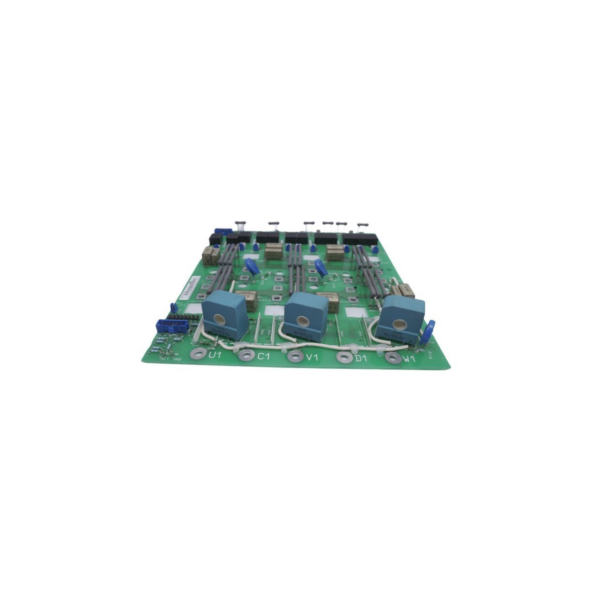
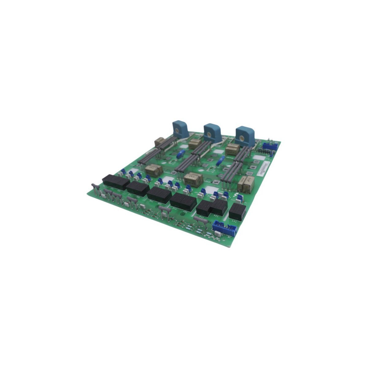
The ABB SDCS-PIN-11 3ADT306100R1, also cataloged as the SDCS-PIN-11 Power Interface Board, operates as a dedicated hardware component for power distribution monitoring and thyristor firing pulse generation within DCS600 drive architectures. Configured as an internal layer interface, the unit processes raw voltage references and converts system control algorithms into synchronous electrical triggering paths for power semiconductor arrays. The module routes diagnostic feedback signals across backplane interconnections while external communication channels leverage localized Ethernet router routing structures to manage remote system inquiries.
Hardware Specifications
| Parameter | Specification |
|---|---|
| Model | SDCS-PIN-11 3ADT306100R1 |
| Brand | ABB |
| Origin | SWEDEN |
| Weight | 0.66 kg |
| Dimensions | 28.1 x 25.4 x 4.0 cm |
| Operating Temp | 0 to +55 deg C (Standard operational enclosure thresholds) |
| Power Consumption | Nominal internal bus logic drawing limits |
| Module Type | Power Interface Board |
| Series Range | DCS600 Series |
| System Classification | DCS / Industrial Drive Control |
| HS Code | 8537101190 |
| Communication Protocols | Multi-protocol network integration compatibility |
Industrial Control & Drive Technical Profiles
The module hardware layout dictates structural bus routing configurations, which directly optimize the backplane bus communication velocity across the host controller chassis. Operators evaluate system logic parameters via dedicated diagnostics loops, while field engineers maintain standard firmware flash compatibility matrices across successive module updates to prevent baseline functional divergence. The internal circuitry links to alternative network trees such as Profinet or EtherNet/IP deterministic networks, which systematically isolate the processing core from external traffic spikes. This electrical routing structure stabilizes the thyristor pulse synchronization cycle and reduces timing drift during prolonged continuous deployment loops.
Frequently Asked Questions
Q: How do installation technicians ensure firmware flash compatibility during an active module replacement process?
A: Field engineers must match the underlying system firmware revision code with the hardware platform parameters via the drive engineering tools. Mismatched baselines prevent the host system from recognizing the power configuration registers, which systematically trips the circuit safety lockouts.
Q: What mechanisms protect the communication channels against runtime packet drops?
A: The board design routes timing-critical control packets over dedicated internal channels using synchronous bus interfaces. While the Ethernet router interface handles general monitoring traffic, the hardware layer enforces deterministic bandwidth allocations for priority firing loops.
Field Installation Guidelines
| Weight | 1 kg |
|---|---|
| Country of Origin | Sweden |
| Dimension | 28.1 x 25.4 x 4 cm |
Reviews
There are no reviews yet.