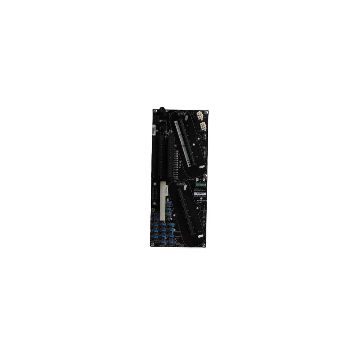
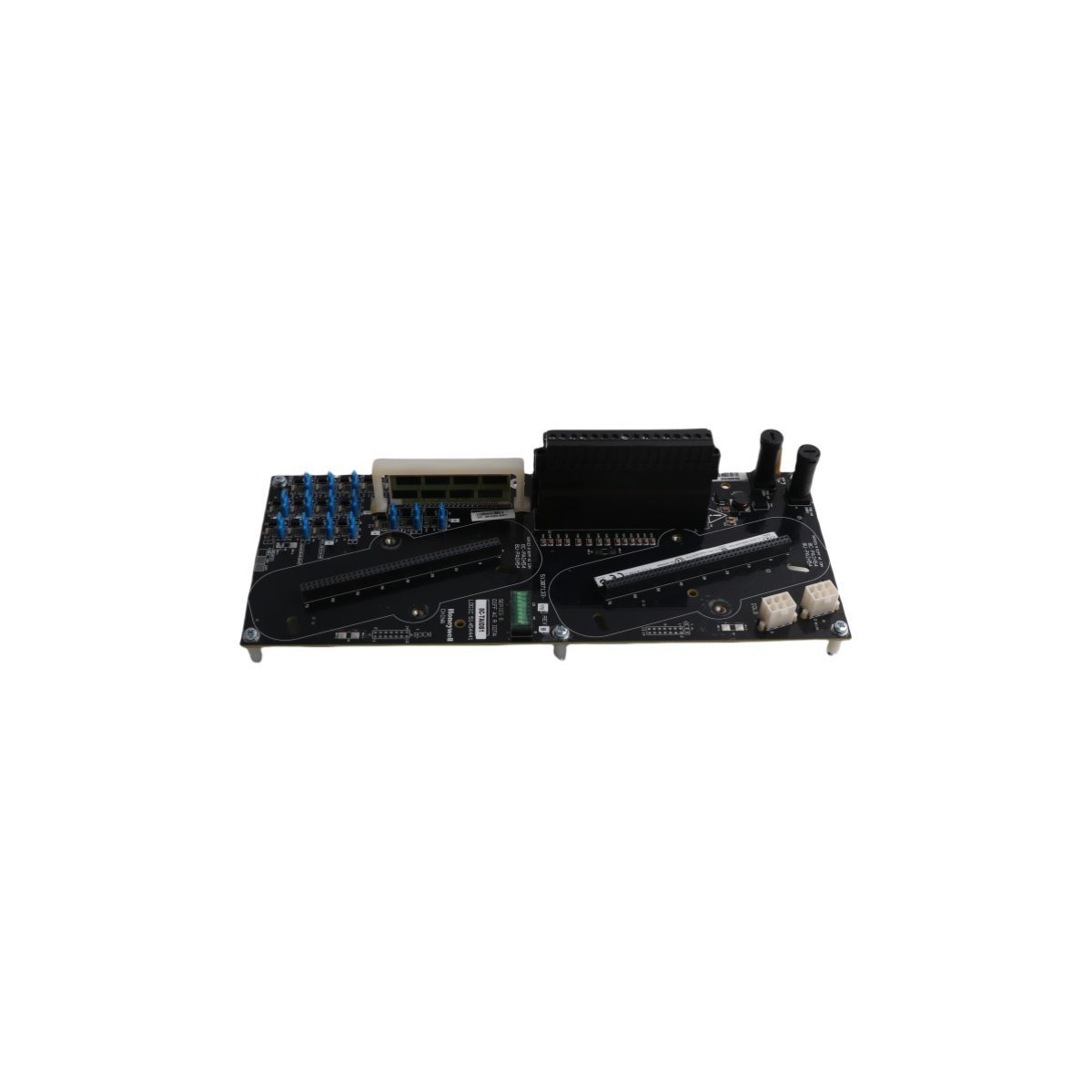
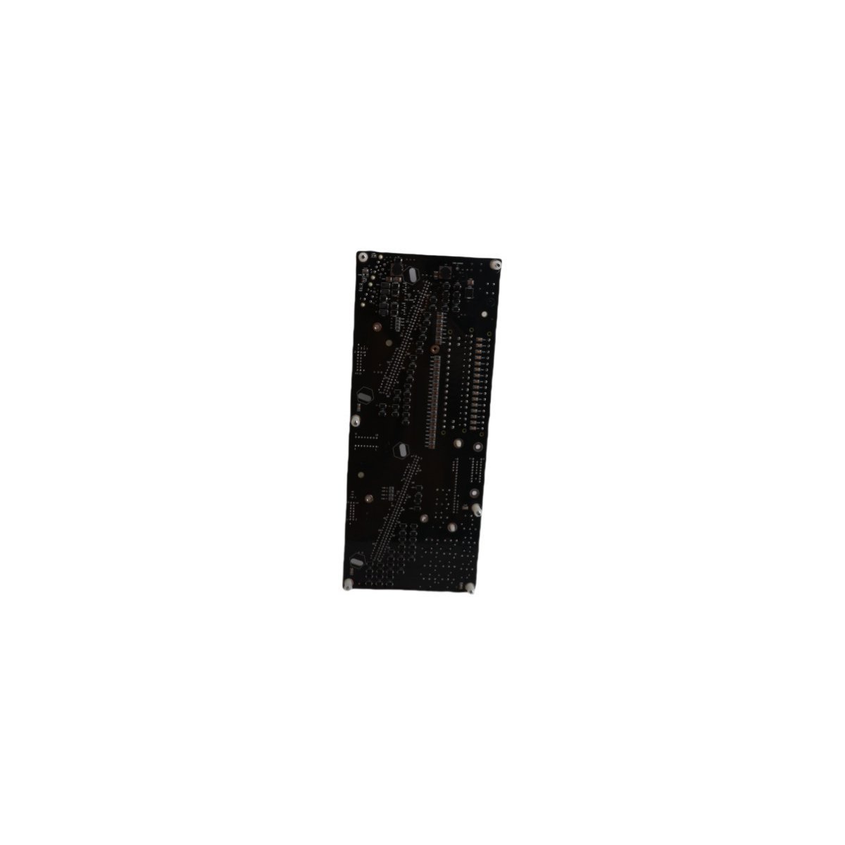
8C-TAIDB1 51307133-175 Honeywell Series 8 Interface Module Backplane
Sale!
In stock: Honeywell 8C-TAIDB1 51307133-175 Interface Module Backplane for Series 8 DCS systems. Brand New item in Original Stock, ready for immediate Global Shipping.
The Honeywell 8C-TAIDB1 51307133-175, also cataloged as the 8C-TAIDB1 Interface Module Backplane, operates as a dedicated hardware component for physical signal routing and field termination routing within Series 8 DCS platforms.
Hardware Specifications
Parameter
Specification
Model
8C-TAIDB1 51307133-175
Brand
Honeywell
Origin
USA
Weight
0.38 kg
Dimensions
29.5 x 12.0 x 7.5 cm
Operating Temp
Standard industrial limits (0 to 60 deg C nominal)
Power Consumption
Backplane bus powered
Product Range
Series 8
System Classification
DCS (Distributed Control System)
Mounting Format
Cabinet I/O Carrier / DIN-Rail
HS Code
8537101190
Process Control & Channel-to-Channel Isolation
The backplane routing architecture routes field signals from analog and digital modules directly into the C300 controller structure. While field transmitters utilize the standard 4-20 mA HART loop protocol for continuous parameter telemetry, this interface backplane isolates individual I/O paths to maintain total channel-to-channel isolation. Internal power traces distribute stable voltage across mounted modules, while solid ground planes attenuate common-mode noise and prevent cross-channel signal interference across high-density field terminal blocks.
Frequently Asked Questions
Q: Does the 8C-TAIDB1 backplane allow technicians to replace attached I/O modules during active power state?
A: Technicians can hot-swap individual I/O modules directly on the carrier, provided the backplane retains solid earth grounding and the replacement module matches the slot configuration parameters.
Q: How do field wiring teams ensure proper grounding across the backplane shield terminals?
A: Installers connect incoming signal cable shields directly to the designated drain terminals on the terminal block assembly, while ensuring the central ground lug attaches to the main cabinet earth bar with low-impedance copper strap.
Field Installation Guidelines
Installers mount the backplane assembly onto the vertical enclosure mounting plate using standard M4 screws or heavy-duty DIN-rail clips. Technicians must verify that the enclosure structural frame establishes a low-impedance bond to earth ground before attaching field wiring harness assemblies.
Wiring personnel strip signal leads according to terminal block specifications and land individual conductors onto the screw-clamp connectors. Engineers must segregate low-voltage instrument signal lines from high-voltage power lines inside the wire ducts, while routing external serial and ethernet communication lines through distinct conduits to prevent electromagnetic cross-talk.
Weight
0.38 kg
Country of Origin
USA
Dimension
29.5 x 12 x 7.5cm
Reviews
There are no reviews yet.
Be the first to review “8C-TAIDB1 51307133-175 Honeywell Series 8 Interface Module Backplane” Cancel reply




Reviews
There are no reviews yet.