
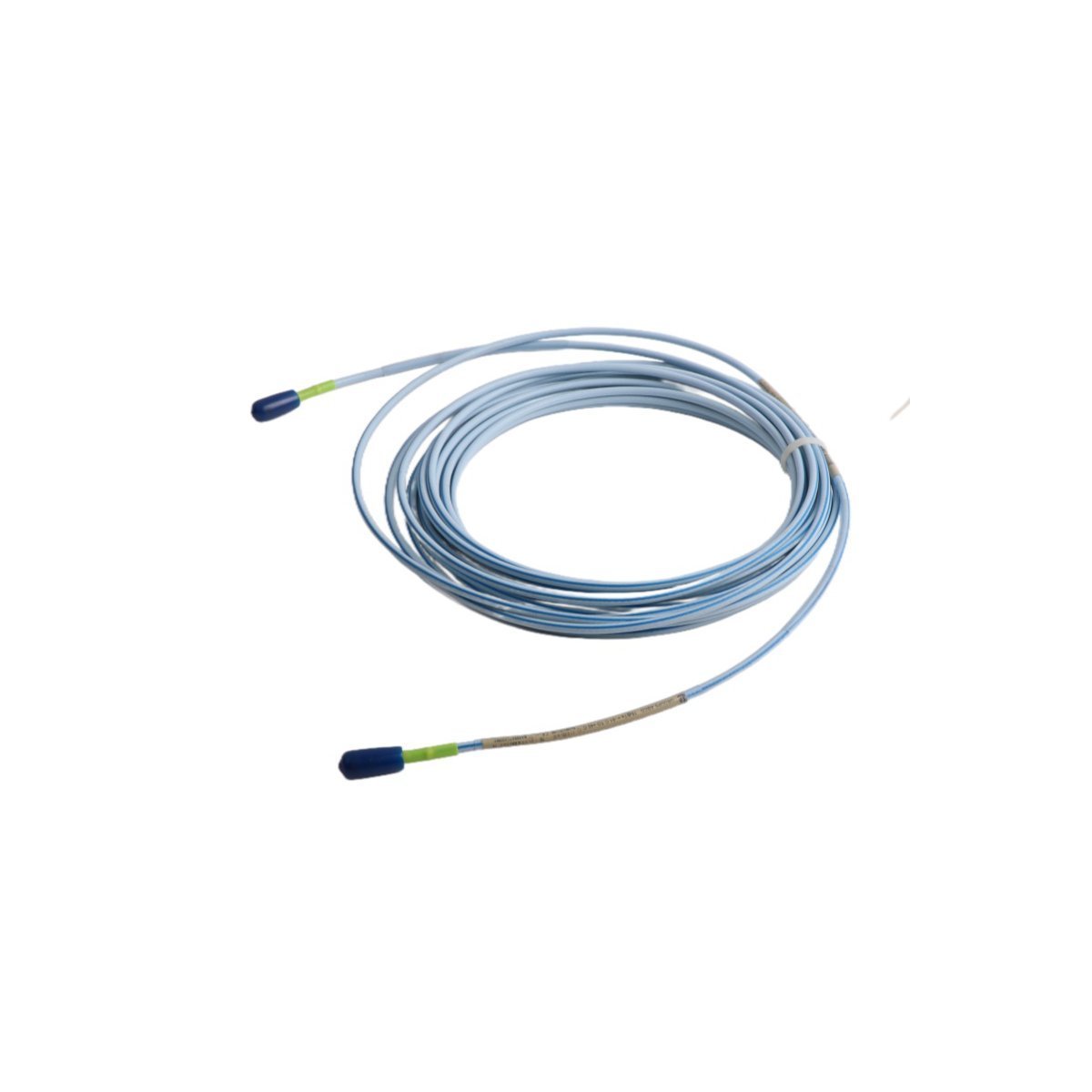
330854-080-24-05 Bently Nevada 3300 XL 25 mm Extension Cables
Sale!Order the 330854-080-24-05 Bently Nevada 3300 XL 25 mm extension cable. Brand New, Original Stock available with fast Global Shipping for TSI applications.
99 in stock


Bently Nevada 330854-080-24-05 3300 XL 25 mm Extension Cable
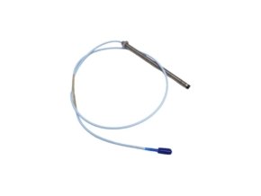
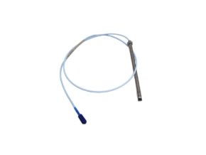
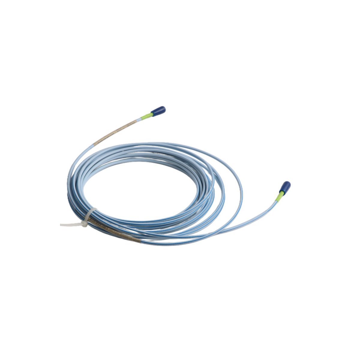
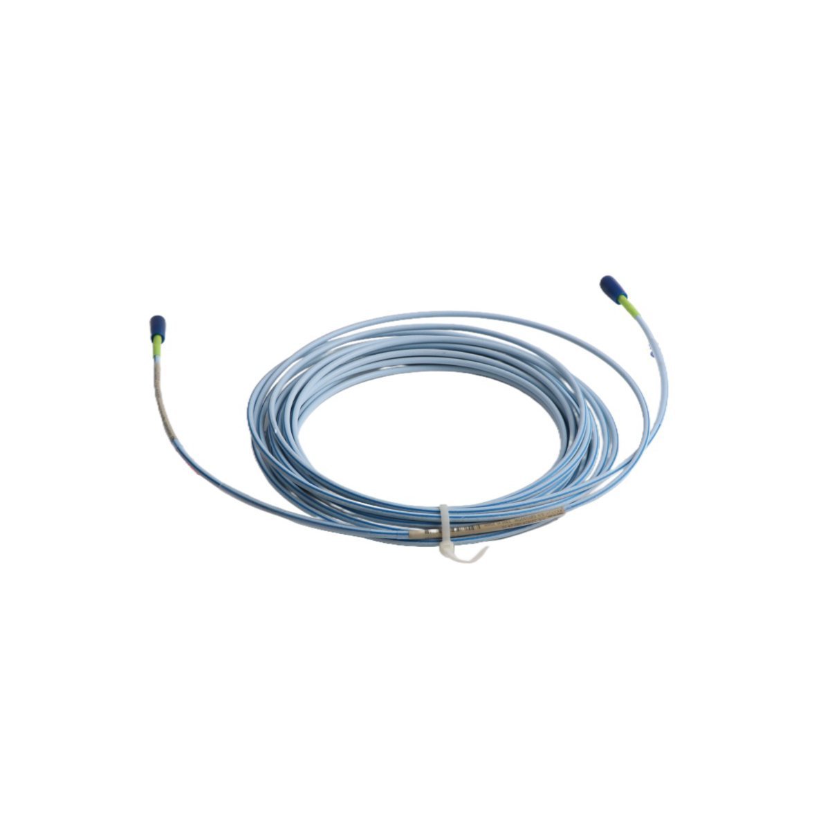
The Bently Nevada 330854-080-24-05, also cataloged as the 330854 3300 XL 25 mm Extension Cable, operates as a dedicated hardware component for high-temperature signal routing between proximity probes and Proximitor Sensors within TSI platforms.
Hardware Specifications
| Parameter | Specification |
|---|---|
| Model | 330854-080-24-05 |
| Brand | Bently Nevada |
| Origin | USA |
| Weight | 0.08 kg |
| Dimensions | 112 cm x 1.5 cm x 1.2 cm |
| Operating Temp | Up to +200 deg C continuous (+250 deg C excursion limit) |
| Power Consumption | Passive physical media (0 W power draw) |
| Cable Length | 8.0 meters (26.2 ft) |
| System Compatibility | 3300 XL 25 mm Proximity Transducer System |
| Sealing Technology | High-Temperature FluidLoc cable construction |
| Linear Range Capability | 12.7 mm (500 mils) differential expansion span |
| Sensitivity / Scale Factor | 0.787 V/mm (20 mV/mil) system scale factor |
Eddy-Current Signal Conditioning and Rotor Dynamics Transmission
The 330854 extension cable couples the high-frequency RF magnetic excitation field between the 25 mm proximity probe tip and the Proximitor unit. Because differential expansion measurements in steam turbines demand exceptional thermal stability, the specialized fluoropolymer insulation prevents capacitance shifts across severe temperature fluctuations. Consequently, the signal link preserves the linear scale factor integrity across the 12.7 mm measurement span.
During initial machinery setup, field engineers execute gap voltage validation to anchor the baseline signal. Adjusting the probe position until the raw output registers -10 VDC targets centers the sensor within its linear region, which maximizes measurement headroom. Furthermore, the cable construction provides cross-talk suppression and maintains high noise rejection, enabling accurate tracking of complex rotor dynamics under harsh operating conditions.
Frequently Asked Questions
Q: How does the FluidLoc cable option prevent internal fluid migration along the signal path?
A: The FluidLoc cable construction uses internal blocking barriers along the conductor bundle. As a result, it stops oil and moisture wicking through the cable core, which maintains signal insulation resistance in harsh environment enclosures.
Q: How do field technicians inspect signal integrity along the 8.0-meter extension cable?
A: Technicians disconnect the cable at both ends and measure center-conductor resistance using a standard digital multimeter. Consequently, establishing baseline continuity and checking outer shield isolation against ground confirms that the cable maintains proper electrical properties.
Field Installation Guidelines
Installers must route the 8.0-meter extension cable through protective metal conduit, keeping it separate from high-voltage AC power lines and variable frequency drive (VFD) output runs. Furthermore, technicians must observe a minimum bend radius of 25.4 mm (1.0 in) to protect the internal coaxial shielding from mechanical fatigue.
When making field connections, technicians press the ClickLoc coaxial connectors together until they click into place, then secure the outer protective sleeve over the junction. This step prevents moisture ingress and physical contamination at the connector interface.
System integrators must ground the cable shield at the Proximitor Sensor housing terminal block only. Leaving the shield ungrounded at the probe end breaks potential ground loops across the machine train structure, which optimizes signal-to-noise performance.
| Weight | 0.08 kg |
|---|---|
| Country of Origin | USA |
| Dimension | 112 x 1.5 x 1.2cm |



Reviews
There are no reviews yet.