
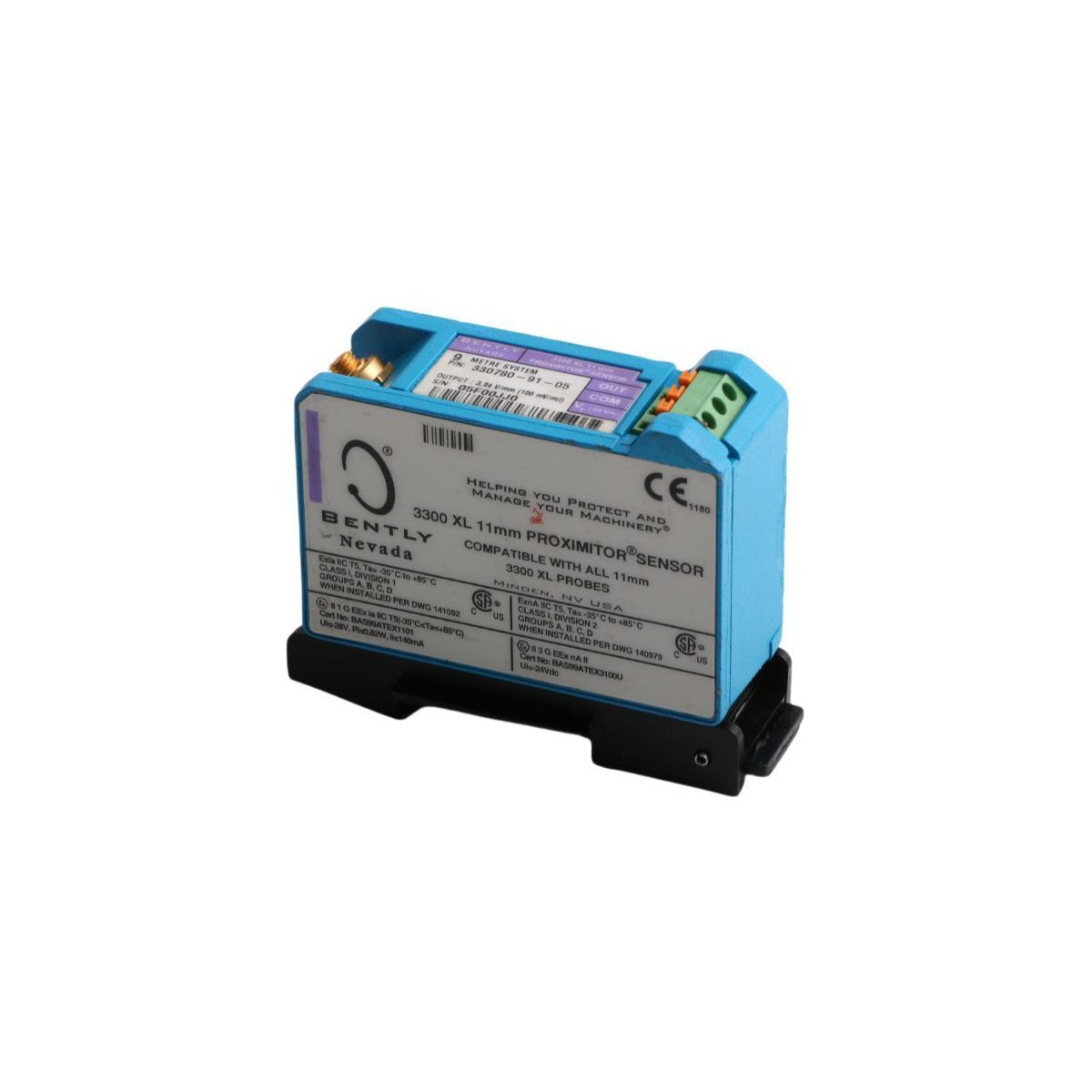
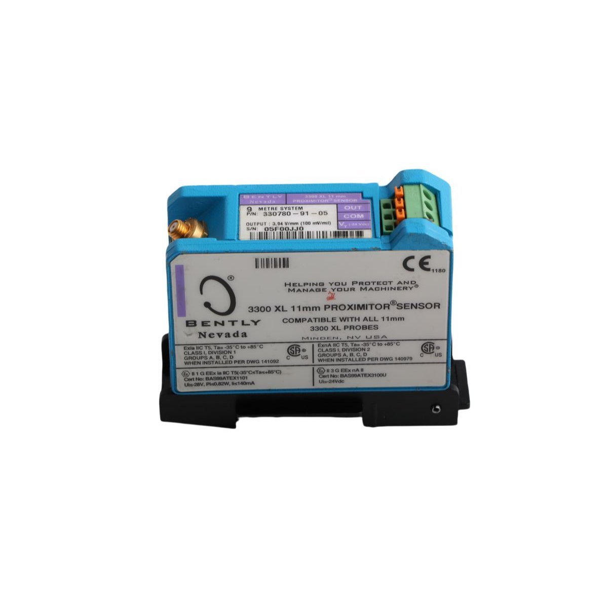
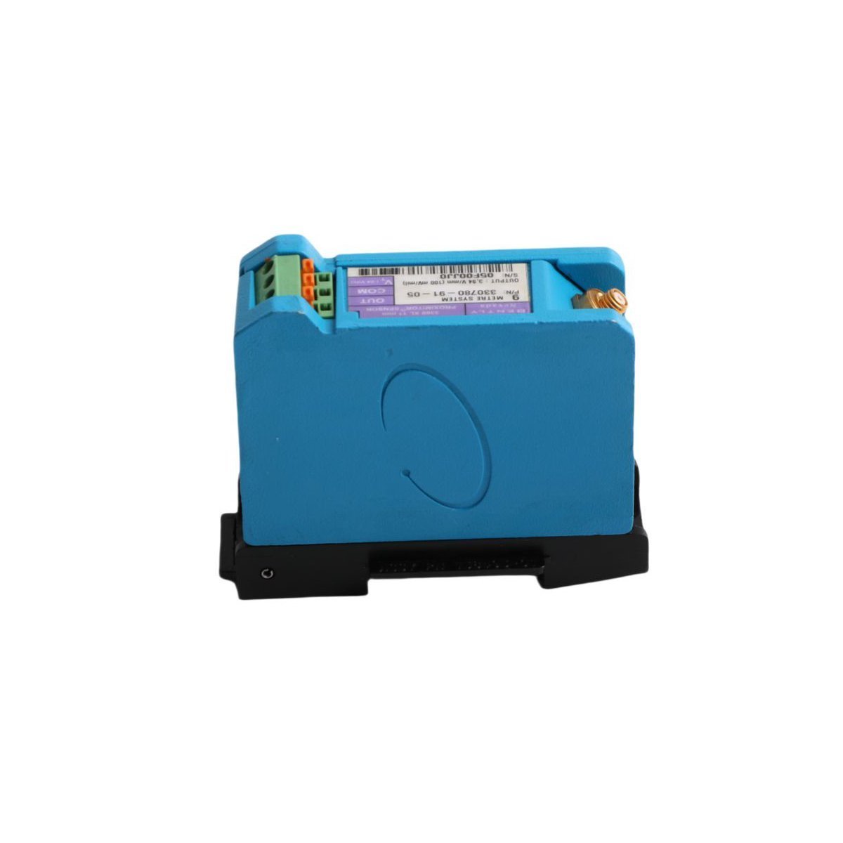
Bently Nevada 330780-91-05 3300 XL 11 mm Proximitor Sensor
Sale!Order the 330780-91-05 Bently Nevada 3300 XL 11 mm proximitor sensor. Brand New, Original Stock ready for fast Global Shipping for TSI system installations.
99 in stock


Bently Nevada 330780-91-05 3300 XL 11 mm Proximitor Sensor
The Bently Nevada 330780-91-05, also cataloged as the 330780 3300 XL 11 mm Proximitor Sensor, operates as a dedicated hardware component for converting physical probe tip clearance into proportional voltage signals within TSI platforms.
Hardware Specifications
| Parameter | Specification |
|---|---|
| Model | 330780-91-05 |
| Brand | Bently Nevada |
| Origin | USA |
| Weight | 0.24 kg |
| Dimensions | 8.7 cm x 3.4 cm x 7.0 cm |
| Operating Temp | -51 deg C to +100 deg C (-60 deg F to +212 deg F) |
| Power Consumption | Requires nominal -24 VDC supply (12 mA typical current draw) |
| System Length | 9.0 meters (29.5 ft) total system length |
| Mounting Options | 35 mm DIN-rail mounting or traditional four-hole panel mounting |
| Field Wiring Terminals | SpringLoc terminal strips accepting 0.2 to 1.5 mm2 (16 to 24 AWG) wire |
| Transducer Type Compatibility | 3300 XL 11 mm proximity probe and matching extension cable |
| EMI Protection Rating | European CE mark compliant with enhanced RFI/EMI shielding |
Eddy-Current Transducer Scaling and Voltage Signal Behavior
The 330780 Proximitor Sensor conditions high-frequency radio frequency (RF) signals emitted from an 11 mm eddy-current probe tip. When the distance between the probe and target rotor surface shifts, target metal eddy currents alter the RF carrier amplitude. The internal circuitry demodulates this amplitude fluctuation, and it outputs a linear DC voltage directly proportional to target gap distance.
During field setup, technicians perform gap voltage validation to ensure accurate rotor positioning. Setting the probe gap until output terminal voltage reads exactly -10 VDC targets positions the system at the midpoint of its linear range. Consequently, this linear baseline prevents signal saturation, preserves cross-talk suppression between adjacent channels, and enables precise dynamic tracking of severe rotor dynamics during machinery acceleration.
Frequently Asked Questions
Q: How do field technicians verify correct probe gap voltage (-10 VDC targets) during setup?
A: Field technicians connect a calibrated multimeter across the sensor output and common terminals while applying -24 VDC power. They then mechanically adjust the probe depth relative to the target shaft until the multimeter measures -10 VDC, which verifies optimal linear range positioning.
Q: How do the SpringLoc terminal connectors simplify field wiring and prevent loose connections?
A: The SpringLoc terminal strips clamp signal conductors using constant spring pressure rather than screw threads. Technicians simply insert stripped wire ends into the terminal cavity, which speeds up wiring procedures and maintains reliable electrical contact under severe machine vibration.
Field Installation Guidelines
Installers must mount the Proximitor Sensor on either a 35 mm DIN rail or a flat, grounded metal panel inside a weather-tight enclosure. Because the unit features enhanced RFI/EMI shielding, it does not require special isolated mounting plates to meet European CE directives; however, installers must maintain proper grounding logic.
Strip signal wire ends to 8 mm and insert them directly into the SpringLoc terminal blocks. Route field cables through dedicated signal conduits while isolating them from high-voltage motor feeds or variable frequency drive (VFD) output lines.
Ground the coaxial cable shield at the Proximitor Sensor terminal block end only. Leaving the sensor shield ungrounded at the probe end isolates the signal loop, which effectively suppresses ground loops across the machine framework.
| Weight | 0.24 kg |
|---|---|
| Country of Origin | USA |
| Dimension | 8.7 x 3.4 x 7cm |


Reviews
There are no reviews yet.