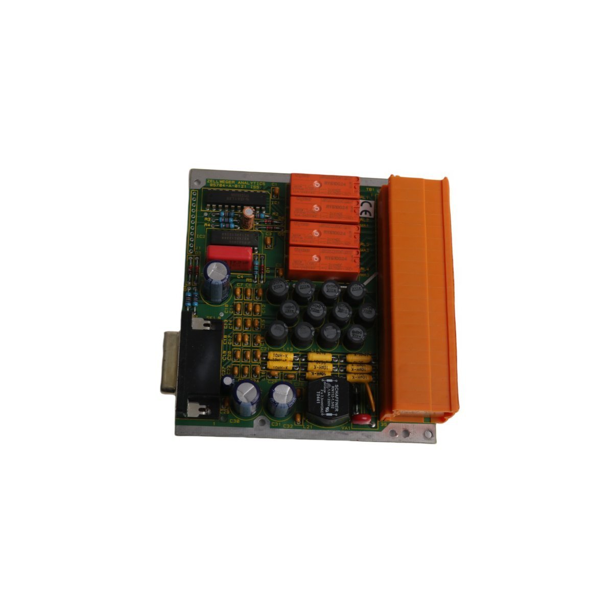
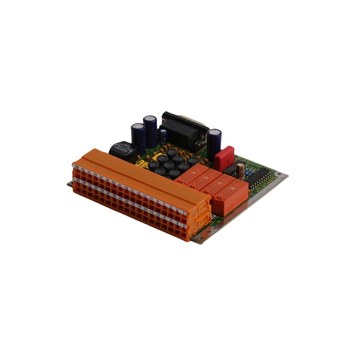
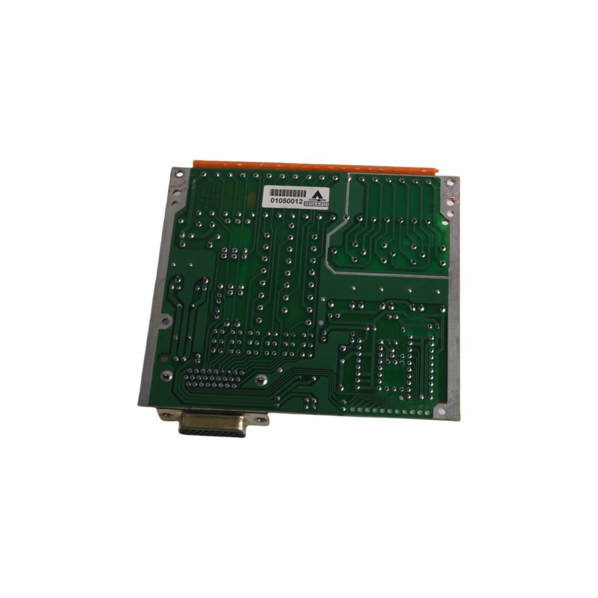
Buy the Honeywell 05704-A-0121 Analytics Quad Relay Interface Card. Brand New in Original Stock with Global Shipping. Features four isolated contact outputs for DCS networks.
The Honeywell 05704-A-0121, also cataloged as the 05704-A-0121 Analytics Quad Relay Interface Card, operates as a dedicated hardware component for discrete contact output signal execution within Experion PKS platforms.
Hardware Specifications
Parameter
Specification
Model
05704-A-0121
Brand
Honeywell
Origin
USA
Weight
0.22 kg
Dimensions
11.8 cm x 13.1 cm x 2.4 cm
Operating Temp
0 deg C to +60 deg C
Power Consumption
Backplane bus powered
Product Type
Analytics Quad Relay Interface Card
System Series
Experion PKS / Control System
Output Type
4 Electromechanical Relay Contact Sets
Bus Communication
Integrated rack backplane bus
Channel-to-Channel Isolation and Relay Contacts
Engineers integrate the 05704-A-0121 card into control racks to drive localized alarm annunciators and trip actuators. Galvanic isolation barriers separate internal backplane processing logic from field contact loops, which prevents external electrical noise or voltage surges from damaging central CPU circuits. The onboard relay channels switch low-voltage AC or DC circuits directly, while dedicated suppression diodes reduce inductive contact arcs during coil de-energization. Consequently, this isolation maintains signal path integrity across all four independent relay outputs.
Frequently Asked Questions
Q: How does channel-to-channel isolation protect control backplane electronics?
A: Internal optocouplers physically isolate backplane logic lines from field relay wiring. Therefore, field short circuits or voltage transients cannot pass backward into the rack controller.
Q: What procedures should technicians follow during module installation?
A: Operators must remove power from external output wiring circuits before insertion. Installing the board while field loops remain energized risks transient contact arcing and unexpected load activation.
Field Installation Guidelines
Technicians must verify that main system rack power stays off and wear a grounded ESD wrist strap before handling the 05704-A-0121 card. Align the board edges with the enclosure guide channels, and then press the assembly into the backplane connector until the locking levers engage fully. Tighten all chassis retaining screws to ensure proper earth ground continuity through the mounting assembly.
Route field output wires separately from low-level analog input signal cables inside the cabinet raceways to prevent inductive cross-talk. When landing stranded copper conductors onto terminal blocks, technicians must crimp wire ferrules onto conductor tips to guarantee secure mechanical clamping. Maintain a minimum 30 mm vertical clearance around board heat sinks to facilitate natural convection cooling inside the cabinet.
Weight
0.22 kg
Country of Origin
USA
Dimension
11.8 x 13.1 x 2.4cm
Reviews
There are no reviews yet.
Be the first to review “05704-A-0121 Honeywell Experion PKS Analytics Quad Relay Interface Card” Cancel reply





Reviews
There are no reviews yet.