
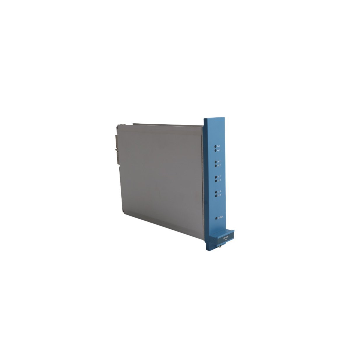
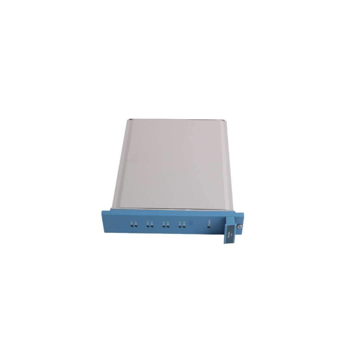
Honeywell FC-USI-0001 V1.0 Safety Manager DCS Universal Safety Interface
Sale!Find Brand New Honeywell FC-USI-0001 V1.0 Safety Manager Interface Modules in Original Stock. We provide fast Global Shipping and complete engineering datasheets.
99 in stock


- Maintenance personnel must verify that panel cutouts match the 3.5 x 22.5 x 17.4 cm chassis footprint before securing the mounting brackets.
- Fasten the ground wire directly from the module grounding stud to the main cabinet earth bar using a 4 mm2 copper conductor to maintain low-impedance protection against surge transients.
- Route field signal cables through dedicated wire troughs, keeping CANopen and Modbus RS-485 data lines isolated from high-voltage AC power wiring by at least 300 mm.
- Tighten all screw terminal connectors to a torque specification of 0.5 Nm to prevent loose physical contacts from causing intermittent signal loss during continuous machine vibration.
Honeywell FC-USI-0001 V1.0 Safety Manager Universal Safety Interface
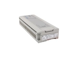
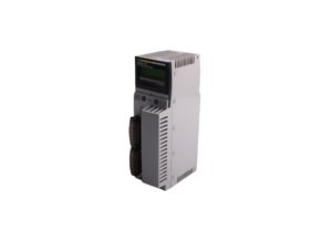
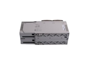
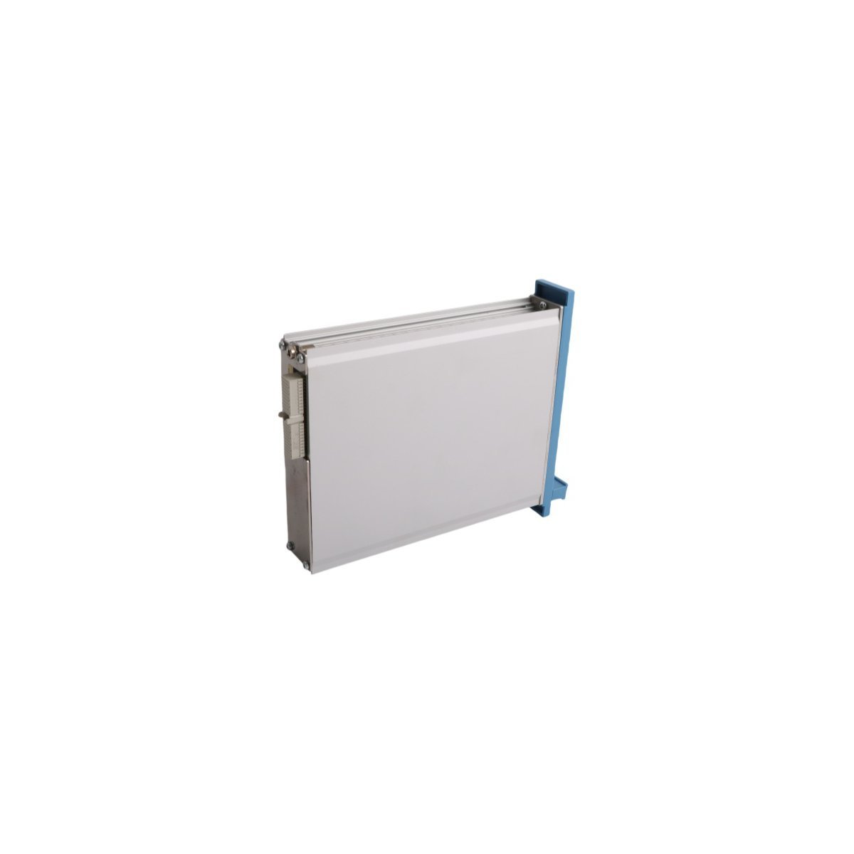
The Honeywell FC-USI-0001 V1.0, also cataloged as the FC-USI-0001 Universal Safety Interface Module, operates as a dedicated hardware component for high-integrity safety system communication and logic interface signal routing within Honeywell Safety Manager platforms.
Hardware Specifications
| Parameter | Specification |
|---|---|
| Model | FC-USI-0001 V1.0 |
| Brand | Honeywell |
| Origin | USA |
| Weight | 0.72 kg |
| Dimensions | 3.5 x 22.5 x 17.4 cm |
| Operating Temp | -20 to 70 deg C |
| Power Consumption | 5 W nominal |
| Series | Safety Manager Series |
| Module Type | Universal Safety Interface |
| Field I/O Count | 8 Inputs / 8 Outputs |
| Communication Protocols | Modbus RTU / CANopen |
| System Platform | Safety Manager / DCS Integration |
| HS Code | 8537101190 |
Fieldbus Protocols & Channel Isolation
Engineers integrate the FC-USI-0001 V1.0 module to establish deterministic data exchange between process controllers and safety instrumentation. The onboard processor manages Modbus RTU and CANopen communication lines while galvanically isolating field channels from internal logic buses. Furthermore, internal signal conditioning circuitry limits cross-talk and transient interference, which ensures steady loop integrity across 4-20 mA HART transmitter links and safety-critical digital I/O points.
Frequently Asked Questions
Q: How do field technicians verify communication link status on the FC-USI-0001 V1.0 interface?
A: Field technicians observe the diagnostic status LEDs on the front panel, which indicate active CANopen bus polling, Modbus frame transmission, and individual channel fault conditions in real time.
Q: Does the FC-USI-0001 V1.0 require dedicated external termination resistors for CANopen loops?
A: Technicians must install 120 ohm line termination resistors across the physical CAN-H and CAN-L terminals at both end nodes of the trunk cable, which prevents signal reflection and frame errors on high-speed communication runs.
Q: What precautions prevent electrostatic damage when inserting the module into a control chassis?
A: Maintenance engineers must wear an ESD grounding strap clamped to the enclosure grounding point before handling the board, because static charges damage sensitive microcontrollers and isolation optocouplers during physical mounting.
Field Installation Guidelines
| Weight | 0.72 kg |
|---|---|
| Country of Origin | USA |
| Dimension | 3.5 x 22.5 x 17.4cm |
Reviews
There are no reviews yet.