
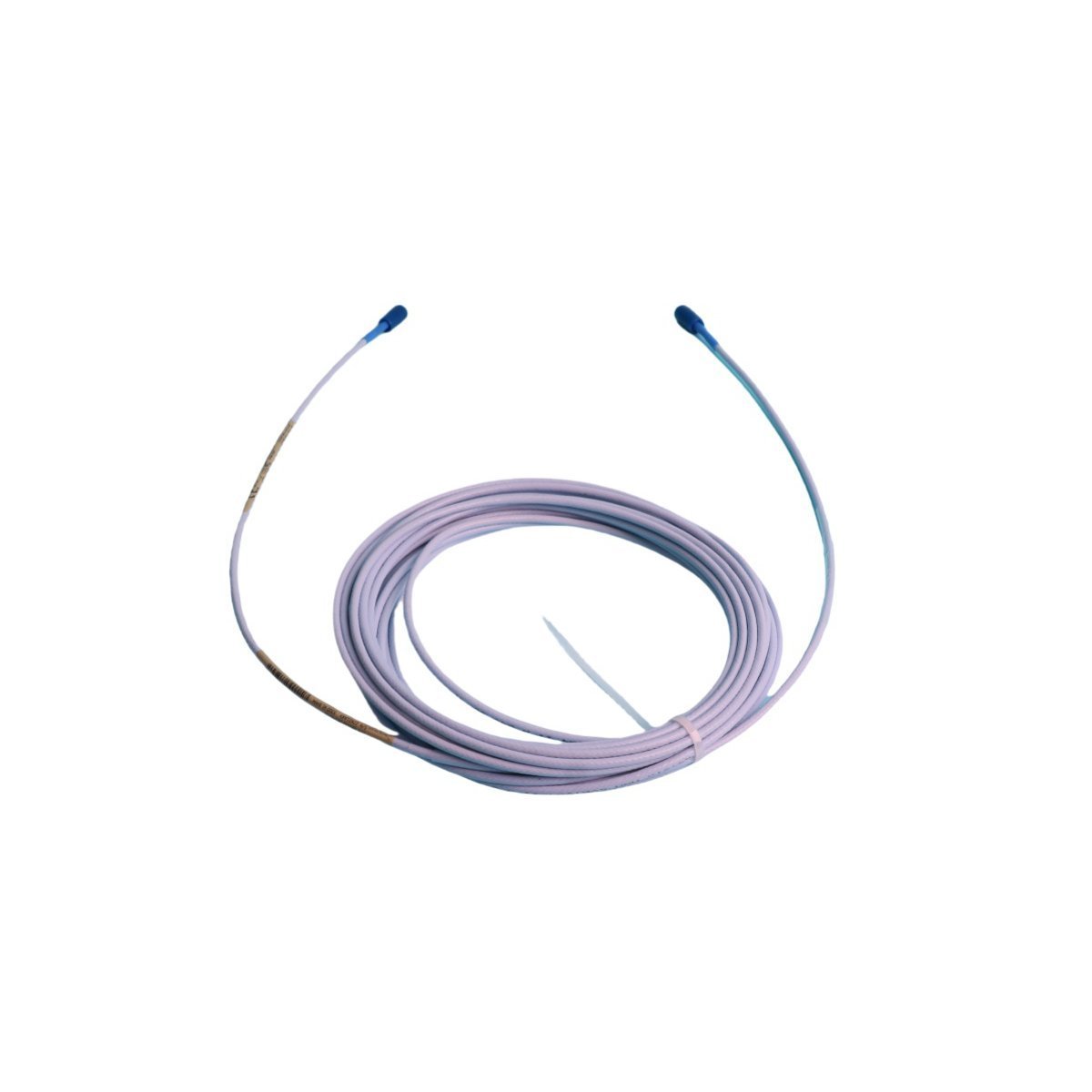
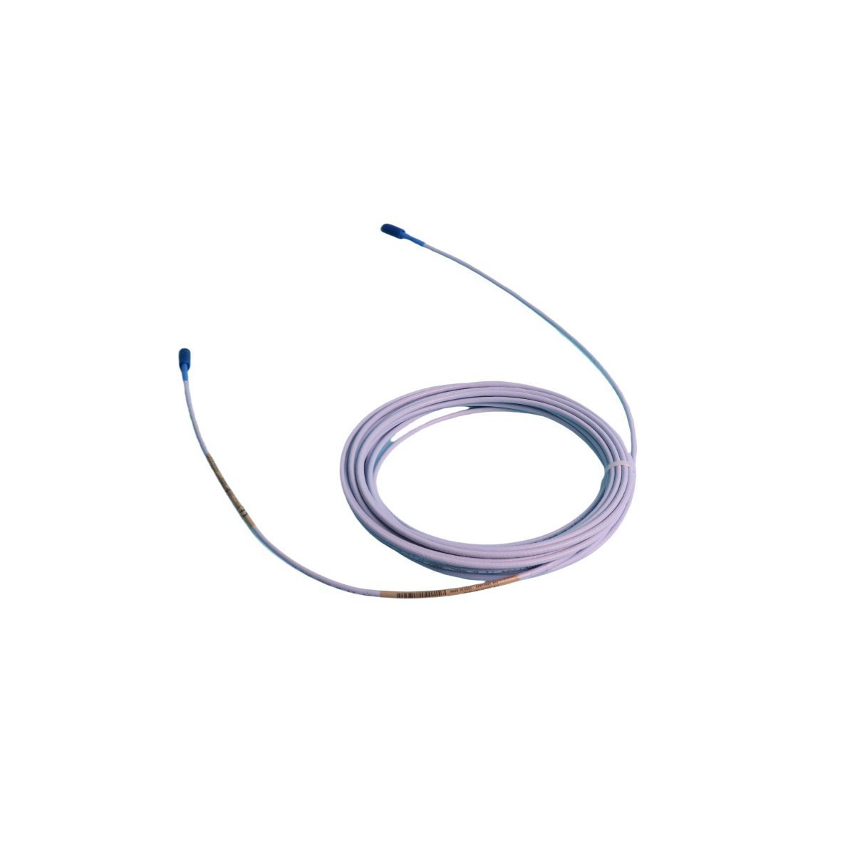
Bently Nevada 330130-085-00-02 3300 XL Extension Cables
Sale!Order the 330130-085-00-02 Bently Nevada 3300 XL extension cable. Verified Brand New, Original Stock components ready for Global Shipping to support TSI field networks.
99 in stock


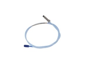
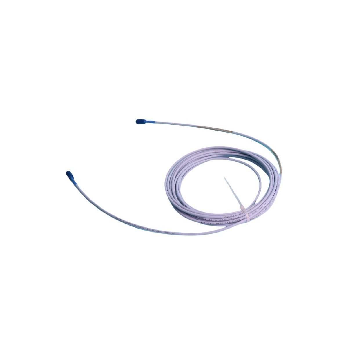
Bently Nevada 330130-085-00-02 3300 XL Standard Extension Cable
The Bently Nevada 330130-085-00-02, also cataloged as the 330130-085-00-02 Standard Extension Cable, operates as a dedicated hardware component for high-frequency coaxial signal transmission within TSI platforms. Field engineers configure this calibrated cable to route analog high-frequency signals between the 3300 XL 8 mm proximity probe tip and the Proximitor Sensor, maintaining precise electrical length matches across the sensor circuit.
Suffix Breakdown & Model Matrix
| Option Code | Selected Value | Engineering Description |
|---|---|---|
| Cable Length Option (085) | 8.5 meters (27.9 feet) | 8.5-meter total physical cable length |
| Armor and Cable Option (00) | Standard Cable (Unarmored) | Standard FEP coaxial cable without stainless steel armor |
| Agency Approval Option (02) | Multiple Approvals | Certified for global hazardous locations via CSA, ATEX, and IECEx standards |
Hardware Specifications
| Parameter | Specification |
|---|---|
| Model | 330130-085-00-02 |
| Brand | Bently Nevada |
| Origin | USA |
| Weight | 0.34 kg |
| Dimensions | 20.5 x 22.2 x 3.5 cm |
| Operating Temp | Standard industrial extension cable range (-51 deg C to +177 deg C) |
| Power Consumption | Passive coaxial conductor (powered via Proximitor Sensor loop) |
| System Compatibility | 3300 XL 8 mm and 5 mm Proximity Transducer Systems |
| Cable Material | FEP outer insulation over coaxial shielding |
| Connector Type | Male and female ClickLoc miniature coaxial connectors |
| Factory Calibration | AISI 4140 high-alloy steel target material |
Eddy-Current Probe Scaling & Signal Interference Suppression
Because coaxial cable length directly alters total system capacitance, field technicians verify overall eddy-current probe scaling after completing intermediate connections. Consequently, installers perform gap voltage validation targeting -10 VDC baseline settings at the transducer output, ensuring the signal remains inside the linear region. Proper cable routing further reinforces cross-talk suppression between closely bundled runs, preventing electrical crosstalk while transmitting raw rotor dynamics data over the 8.5-meter distance.
Frequently Asked Questions
Q: How do field technicians preserve ClickLoc connector integrity in wet or oily environments?
A: Installers apply silicone self-fusing tape or install connector protectors over the mated ClickLoc junctions, which shields the internal coaxial pins against moisture penetration and oil ingress.
Q: Why must field teams avoid cutting or shortening the 330130-085-00-02 extension cable during installation?
A: Altering the physical length changes the electrical capacitance of the cable assembly; as a result, the downstream Proximitor Sensor loses calibration accuracy and output signal linearity across the target range.
Field Installation Guidelines
Technicians install the extension cable by connecting the male ClickLoc plug to the proximity probe lead and snapping the female socket onto the Proximitor Sensor connector. Next, maintenance personnel seat protective connector boots over all exposed coaxial joints, preventing fluid ingress and grounding shorts against metal junction boxes. Installers then secure the FEP cable along cable trays using padded mounting clips, keeping bend radiuses larger than the minimum specified limit. Finally, engineers route the cable away from high-voltage AC lines, eliminating electromagnetic noise coupling into the sensitive vibration measurement loop.
| Weight | 0.34 kg |
|---|---|
| Country of Origin | USA |
| Dimension | 20.5 x 22.2 x 3.5cm |


Reviews
There are no reviews yet.