
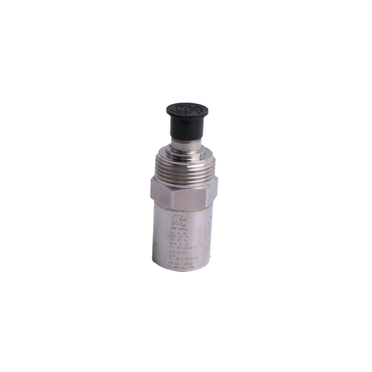
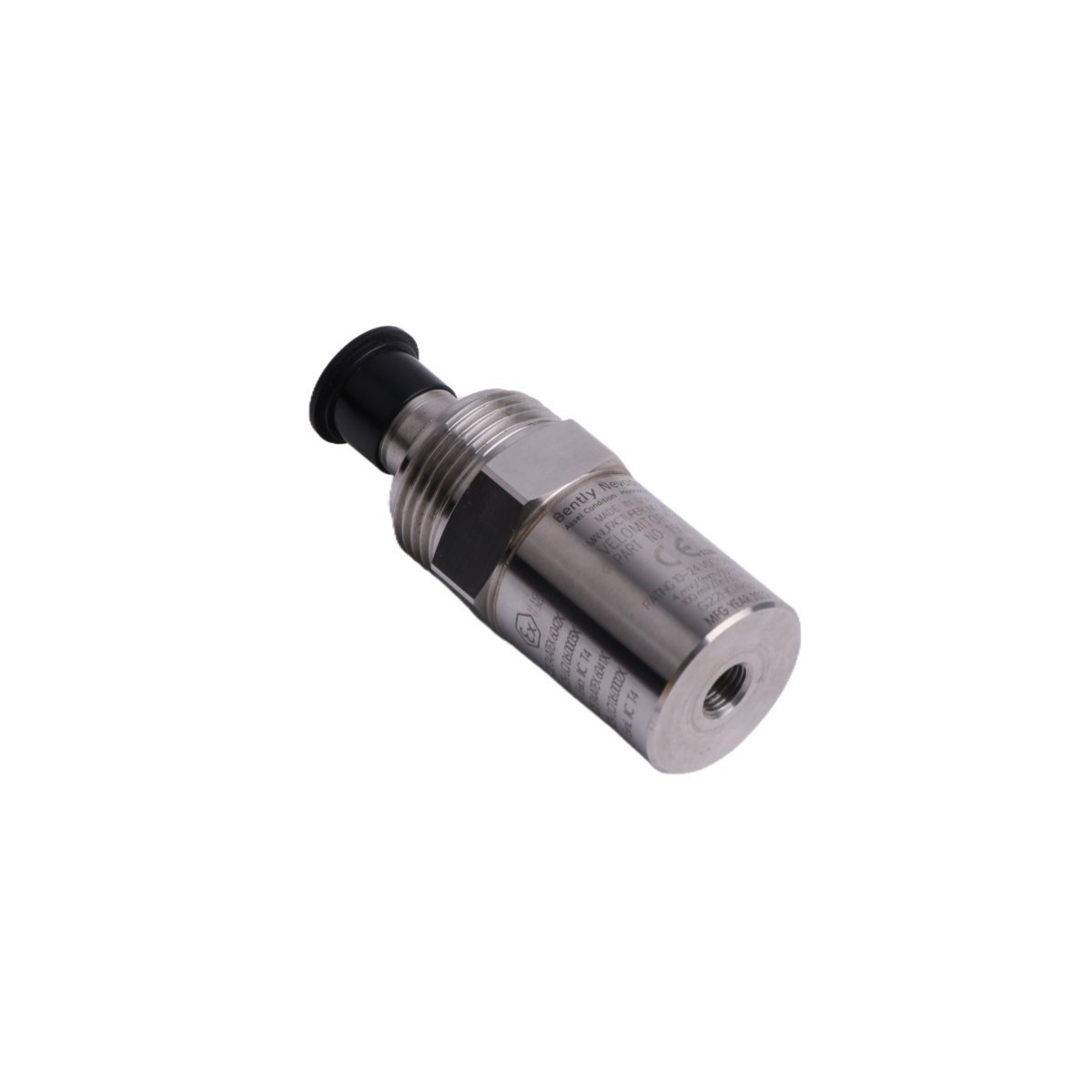
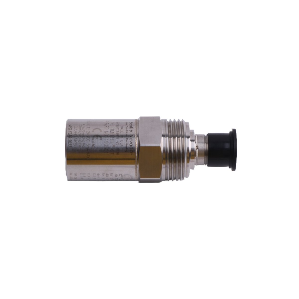
Bently Nevada 190501-04-00-04 Velomitor CT Velocity Transducer
Sale!190501-04-00-04 Bently Nevada Velomitor CT Velocity Transducer. Brand New, Original Stock, Global Shipping. High-precision sensor for cooling tower fan vibration monitoring.
99 in stock


- 190501: Base model for Velomitor CT (Cooling Tower) Velocity Transducer.
- 04: Mounting hardware (4-stud M6 x 1 mounting with 3/8-24 adapter).
- 00: Agency approval (Not required/Standard).
- 04: Mounting adapter configuration.
- Mounting: Bolt the transducer to a rigid, flat surface on the fan casing or motor frame using the M6 or 3/8-24 studs. Ensure the mounting surface is clean and free of paint to maximize mechanical impedance transmission.
- Grounding: Terminate the MIL-C-5015 connector to a shielded twisted-pair cable. Connect the shield to the instrumentation common at the monitor side only to create a single-point ground, which effectively prevents ground loop noise.
- Wiring: Keep the signal cable runs as short as possible. Use rigid conduit for cabling that traverses high-vibration zones to protect against mechanical fatigue and cable insulation breakdown.
- Verification: Confirm the transducer output polarity during installation by gently tapping the housing. A positive signal pulse should register on the monitoring system, which verifies the correct transducer orientation and wiring polarity.
Bently Nevada 190501-04-00-04 Velomitor CT Velocity Transducer
Configured for low-frequency vibration monitoring on cooling tower and air-cooled heat-exchanger fans, the Bently Nevada 190501-04-00-04 (190501 Velocity Transducer) provides direct physical execution of casing vibration velocity measurement across industrial rotating machinery.
Suffix Breakdown & Model Matrix
Hardware Specifications
| Parameter | Specification |
| Model | 190501-04-00-04 |
| Brand | Bently Nevada |
| Origin | USA |
| Weight | 0.55 kg |
| Dimensions | 20.5 x 22.4 x 3.3 cm |
| Operating Temp | -40 deg C to +100 deg C |
| Power Consumption | 18 VDC to 24 VDC (Loop powered) |
| Sensitivity | 3.94 mV/mm/s (100 mV/in/s) |
| Frequency Range | 100 rpm to 300 rpm (Optimized) |
| Impedance | < 400 Ohm |
TSI Monitoring and Signal Integrity
The Bently Nevada 190501-04-00-04 employs a piezo-velocity sensing element to convert mechanical casing vibrations into a proportional electrical signal. Engineers must perform precise eddy-current probe scaling if integrating this transducer into a broader TSI system to ensure vibration amplitudes align with the system’s monitor scaling. Technicians perform gap voltage validation (-10 VDC targets) during the calibration of the monitor card to ensure the signal input remains within the linear range. To prevent signal degradation, installers must ensure cross-talk suppression by shielding the signal cable from high-frequency electromagnetic interference generated by adjacent motor drives .
Frequently Asked Questions (FAQ)
Q: Why is the 190501 optimized for the 100 rpm to 300 rpm range?
A: Unlike standard Velomitor sensors designed for higher-speed turbines, the CT version contains a modified internal seismic mass and spring configuration to extend the low-frequency roll-off point, allowing it to capture velocity signals accurately at the lower rotational speeds typical of cooling tower fans.
Q: Does the transducer require an external signal conditioner?
A: No, the 190501 is a loop-powered device. The transducer receives DC power from the monitor module and returns a proportional voltage signal, which simplifies the wiring architecture significantly.
Field Installation Guidelines
| Weight | 0.55 kg |
|---|---|
| Country of Origin | USA |
| Dimension | 20.5 x 22.4 x 3.3cm |



Reviews
There are no reviews yet.