
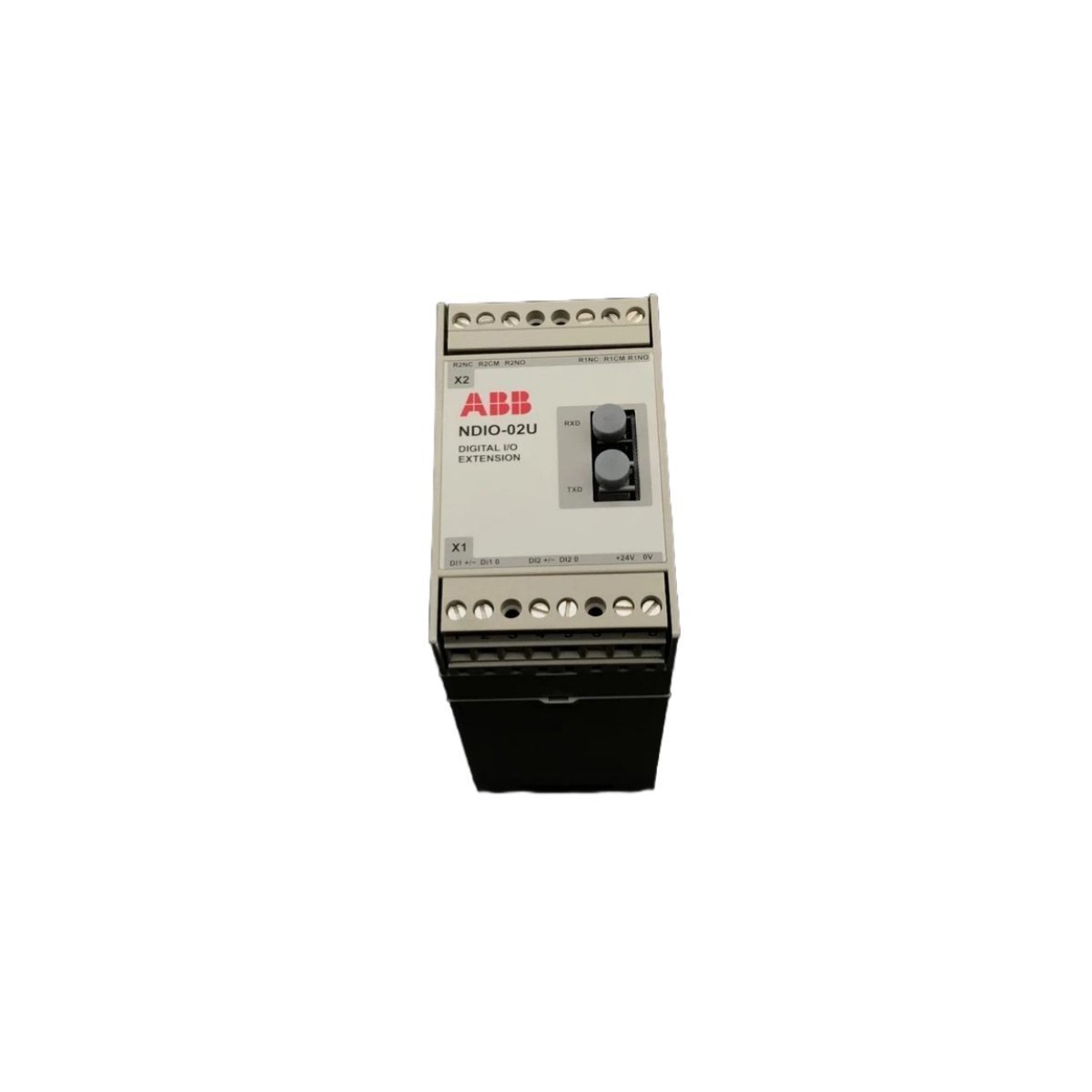
ABB NDIO-02 64129007 DCS Digital I/O Extension Modules
Sale!ABB NDIO-02 64129007 Brand New Original Stock digital I/O extension module. DCS series component ready for immediate deployment with Global Shipping.
99 in stock


ABB NDIO-02 64129007 DCS Digital I/O Extension Module
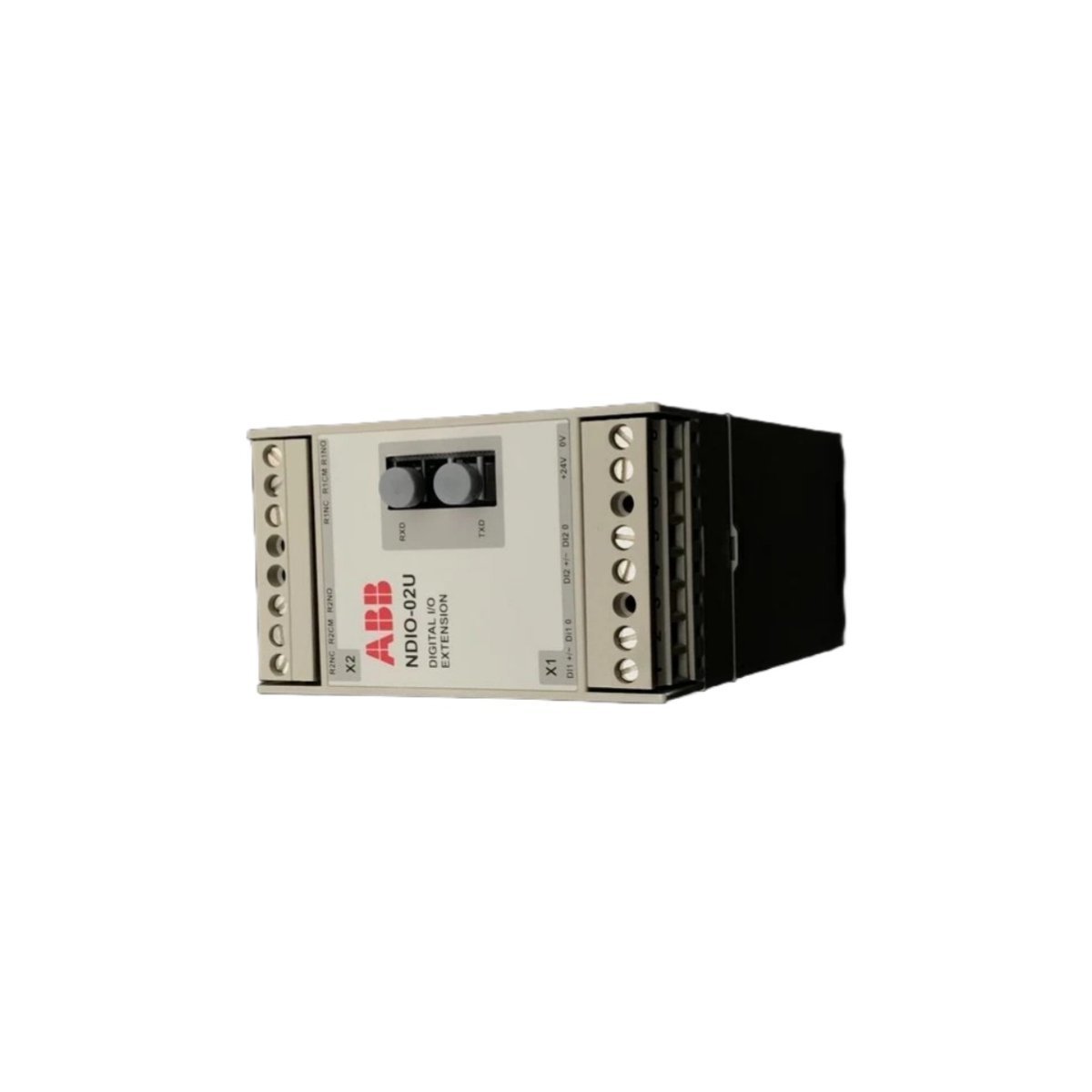
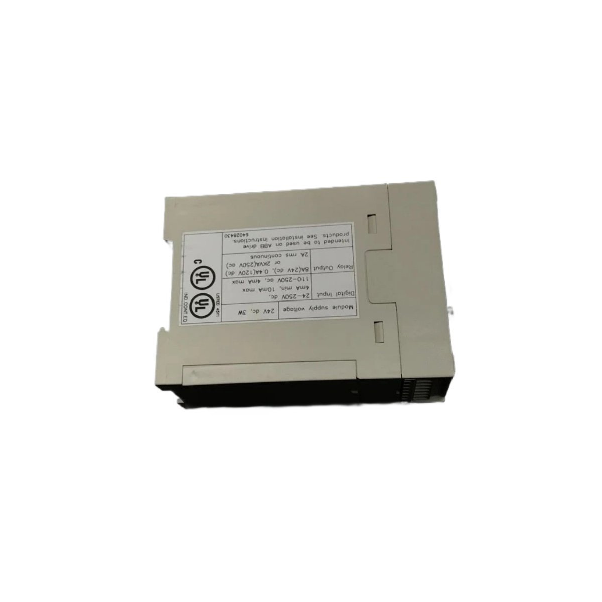
The ABB NDIO-02 64129007, also cataloged as the NDIO-02 Digital I/O Extension Module, operates as a dedicated hardware component for discrete signal processing and contact execution within ABB DCS platforms. Technicians wire field devices directly to the board to sample two digital inputs spanning 24-250 VDC, while internal relay pathways activate two digital outputs rated at 250 VAC. The module conditions incoming discrete logic, filters electrical noise, and transmits binary channel status over the system bus to primary controllers.
Hardware Specifications
| Parameter | Specification |
| Model | NDIO-02 64129007 |
| Brand | ABB |
| Origin | SWEDEN |
| Weight | 2.36 kg |
| Dimensions | 14.5 x 18.0 x 15.0 cm |
| Operating Temp | 0 to +55 deg C |
| Power Consumption | Standard Backplane Bus Power |
| Module Type | Digital I/O Extension Module |
| Series | DCS |
| Digital Inputs | 2 Channels (24-250 VDC) |
| Digital Outputs | 2 Channels (250 VAC) |
| Network Service | Integrated Ethernet Router Communication |
| Commodity Code (HS Code) | 8537101190 |
Firmware Flash Compatibility and I/O Density Scaling
Engineers configure the ABB NDIO-02 64129007 extension card to scale I/O density across distributed rack layouts without exhausting rack real estate. The board synchronizes input states and output control words through high-speed backplane protocols, whereas internal firmware flash compatibility ensures direct handshaking with host DCS processors. Built-in optocouplers isolate high-voltage field wiring from low-voltage bus logic, preventing field surges from damaging sensitive system processors during heavy inductive switching cycles.
Frequently Asked Questions
Q: How do installers ground the digital field wiring shield on this extension module?
A: Field personnel must connect signal cable shielding directly to the cabinet ground bus bar via low-impedance clamps, keeping drain wires as short as possible. Proper shield termination prevents electrical noise from inducing false logic transitions on the 24-250 VDC inputs.
Q: Can maintenance personnel hot-swap this module while backplane power remains active?
A: Operators must isolate all 250 VAC output voltage sources and disconnect main rack power prior to extracting the module. Swapping the hardware under active field loads creates electric arcs that damage terminal connectors and trigger system bus faults.
Field Installation Guidelines
Mount the module vertically inside the control panel enclosure, maintaining clean air paths around the assembly to ensure effective thermal dissipation. Align the module card guides precisely with the rack slots, and then push the unit firmly until the backplane edge connector seats completely. Secure all panel retention screws to prevent vibration-induced dislodgement. Wire the high-voltage 250 VAC relay contacts using separate raceways away from low-voltage communications cabling to block electromagnetic interference. Finally, verify proper screw terminal torque on all field input connections before restoring system power.
| Weight | 1 kg |
|---|---|
| Country of Origin | Sweden |
| Dimension | 14.5 x 18 x 15 cm |




Reviews
There are no reviews yet.