
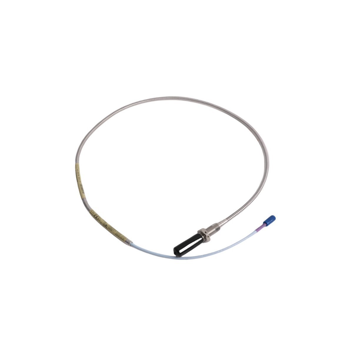
330704-000-100-10-01-05 Bently Nevada 3300 XL 11mm Proximity Sensors
Sale!Get the Bently Nevada 330704-000-100-10-01-05 3300 XL 11 mm probe. Brand New condition, Original Stock guaranteed with Global Shipping for TSI plant monitoring systems.
99 in stock


Bently Nevada 330704-000-100-10-01-05 3300 XL 11 mm Proximity Probes
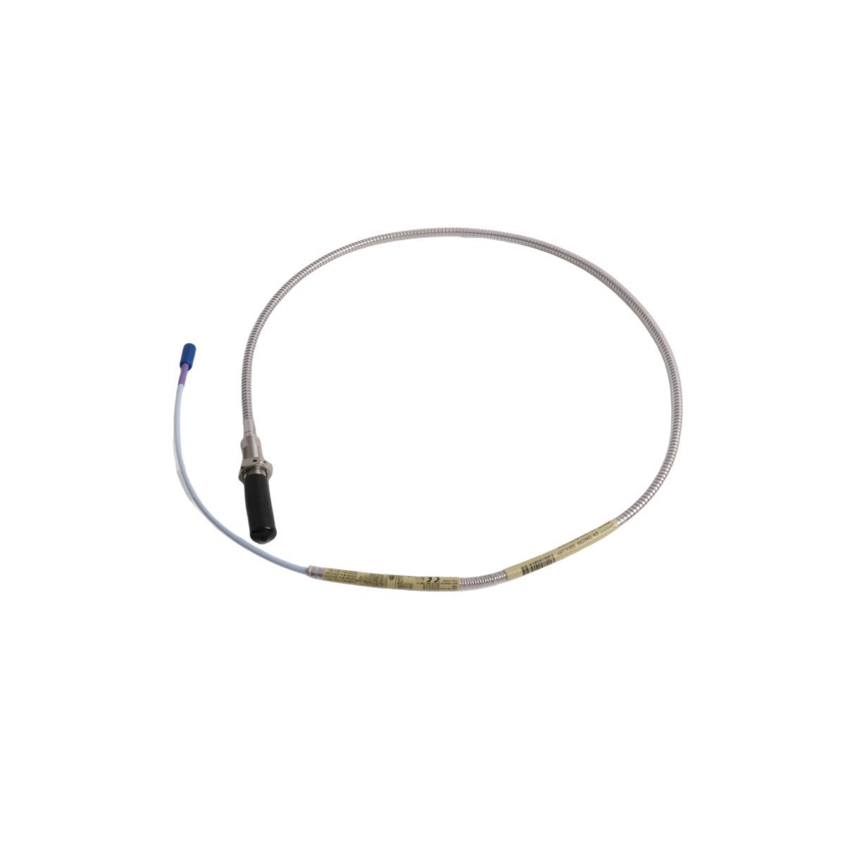
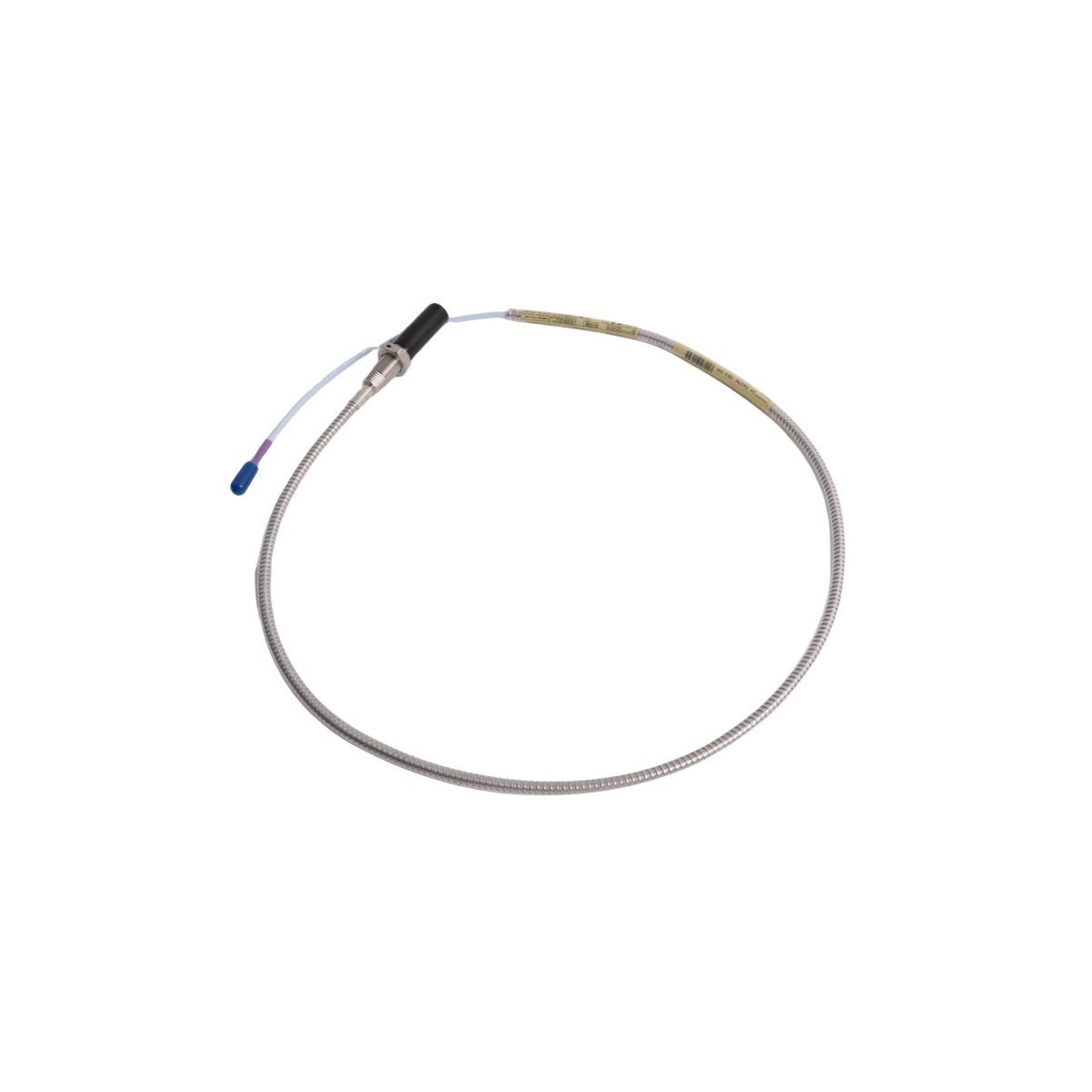
The Bently Nevada 330704-000-100-10-01-05, also cataloged as the 330704 3300 XL 11 mm Proximity Probe, operates as a dedicated hardware component for extended-range axial position monitoring and differential expansion measurement within TSI platforms. The physical sensor head generates an eddy-current field that drives dynamic signal conversion via the companion Proximitor Sensor, while the probe converts target physical gaps directly into calibrated linear voltage outputs at a standard sensitivity of 3.94 V/mm (100 mV/mil).
Suffix Breakdown & Model Matrix
| Option Code | Configuration Parameter | Specification Value |
|---|---|---|
| 330704 | Base Model | 3300 XL 11 mm Proximity Probe |
| -000 | Unthreaded Length Option | 0.0 in (0 mm) |
| -100 | Overall Case Length Option | 10.0 in (254 mm) |
| -10 | Total Length Option | 1.0 meter (3.3 feet) |
| -01 | Connector Option | Miniature coaxial ClickLoc connector |
| -05 | Agency Approval Option | Multiple Approvals (CSA, ATEX, IECEx) |
Hardware Specifications
| Parameter | Specification |
|---|---|
| Model | 330704-000-100-10-01-05 |
| Brand | Bently Nevada |
| Origin | USA |
| Weight | 0.14 kg |
| Dimensions | 1.8 x 1.5 x 110 cm |
| Operating Temp | -51 deg C to +177 deg C |
| Power Consumption | External excitation via Proximitor Sensor (-24 VDC rail) |
| Sensitivity | 3.94 V/mm (100 mV/mil) |
| Probe Head Diameter | 11 mm (0.43 in) |
| Connector Type | ClickLoc miniature coaxial |
| System Compatibility | 3300 XL Transducer System / 3500 Monitoring System |
Machinery Monitoring & Eddy-Current Probe Mechanics
Engineers execute precise eddy-current probe scaling to convert target displacements into proportional DC and AC output voltages across the extended linear range. Technicians verify gap voltage validation (-10 VDC targets) during physical mounting, because positioning the probe tip face to achieve a -10.0 VDC bias sets the target precisely at the midpoint of the voltage envelope.
Because mechanical motion changes the inductive gap geometry, the system continuously analyzes rotor dynamics across high-speed rotating shafts without physical contact. Installers isolate adjacent sensor heads to maintain effective cross-talk suppression, which eliminates inductive interference across multi-channel bearing housings.
Frequently Asked Questions
Q: Does replacing a legacy 7200-series transducer require swapping out all system components?
A: Technicians must execute complete component replacement when upgrading from legacy 7200-series hardware because the 3300 XL 11 mm probe relies on distinct electrical matching characteristics, which causes signal errors if paired with older Proximitor units or extension cables.
Q: How do installers confirm proper physical positioning before locking the mounting jam nut?
A: Operators monitor the DC voltage output at the Proximitor Sensor terminals while they thread the probe body toward the target face, and they secure the jam nut as soon as the multimeter reads the target gap voltage validation point of -10.0 VDC.
Q: Does the 3500 Monitoring System require software modifications when integrating this probe?
A: Field engineers update the rack configuration software parameters because proper system integration requires selecting the specific 11 mm transducer transfer function to scale the 3.94 V/mm sensitivity correctly.
Field Installation Guidelines
Installers handle the probe body with care so that they avoid damaging the 11 mm tip face and integral threads. Screw the probe into the mounting bracket, and route the integral coaxial cable through smooth conduit runs.
Connect a calibrated digital multimeter to the Proximitor raw buffer output terminals. Rotate the probe body to adjust the physical gap, and observe the voltage shift from the negative rail toward zero; stop rotation instantly when the meter reads -10.0 VDC.
Torque the jam nut against the mounting face to lock the probe position. Route the coaxial cable along dedicated cable trays while maintaining a minimum bend radius of 25.4 mm (1.0 inch) so that you prevent internal core fractures. Push the coaxial ClickLoc connector into the mating extension cable plug until the mechanical detent clicks, and slide the protective sleeve over the joint so that you isolate the conductive shell from earth ground.
| Weight | 0.14 kg |
|---|---|
| Country of Origin | USA |
| Dimension | 1.8 x 1.5 x 110cm |



Reviews
There are no reviews yet.